


A NEW CHANGE-SPEED GEAR.
Page 30
If you've noticed an error in this article please click here to report it so we can fix it.
A Résumé of Recently Published Patents.
• It will be quite easy for anyone who has watched a ball bearing at -work to understand the first principle which underlies the transmission gear which is described in patent specification No. 173,899, and even those who have not had that experience may, with but little consideration, fail into line with their more favoured fellows. For, think for a moment what is really happening when a shaft, mounted in an ordinary.
half bearing, is rotating. The shaft carries with it the inner race of the bearing, which rolls upon the balls. They, in their tarn, under pressure from the race, roll upon the outer race, carrying with them tho cage, which, it will be observed, rotates in the same direction as the Tha.ft; and inner race, but more slowly Noy,' imagine that, of a pair of shafts, one of which is driven by the other, one is attached to the race and the other to the ball cage, se that the transmission actually takes place through the components of the bearing, and you have, in its simplest form, the transmission which, at the hands of this inventor, J. H. Dolton, becomes an infinitely vari able change-speed gear. .
To understand the method of effecting a change of speed, it is necessary to exercise our imaginations a little further. Assume thatt the ball bearing is split vertically through its centre, in a plane parallel to the race itself—that is to say, at right angles to the shaft—and imagine that the inner and outer races, although secured, as regards the first, to the shaft, and as regards the second, to some non-rotating casing, are still capable of being moved towards or away from one another. It will not be difficult to realize, we think, that as the two halves of the inner race approach one another, the balls will be forced to run on.a bed of larger diameter, and a corresponding alteration in the, relative speeds of the inner race {or one shaft) and.the ball cage (or.other shaft) will he effected. The outer race is merely split so that it can. accommodate itself to this expanding and contracting movement, and in actual practice its two halves are impelled one to another by springs so as to maintain a suitable pressure between the balls and the inner race
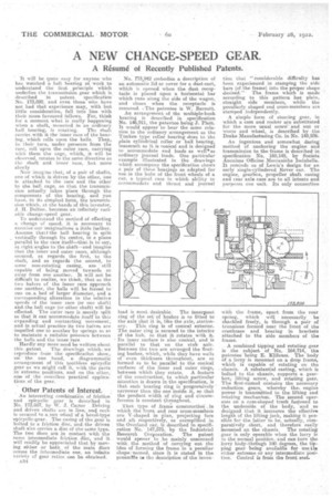
Hardly any more need be written about this patent The drawings which; we reproduce from the specification show,
-• the one hand, adiagrammatic arrangement of this toothless 0p:cyclic gear as we might call it, with the parts in-ea.-drone positions, and on the other, one of the countless practical applications of the gear.
Other Patents of Interest.
An interesting combination of friction and epieyelic' gear is described in No. 173,957, by W, J. Carter Driving and driven shafts are in .line, am4 each is secured to a,stin ieel -et a bevel-type epicyclicageara The casing of the gear is bolted to a friction disc, and -the driven shaft also carries a disc of the same type. The two discsaro in contact with the same intermediate friction . disc, and it will readily be appreciated that by moving either or both of the main .discs across the intermediate one, an infinite veriety of gear ratios can be obtained.
A34 No. r73,942 embodies a description of an automatic lid or cover for a dust-cart, which is opened when the dust receptacle it placed upon a horizontal bar which runs along the side of the wagon: and closes when the receptacle is removed. The patentee is W. Barnett.
An arrangement of the multiple-bush bearing is described in specification No. 146,911, the patentee being J. Platt. It would appear to bear the same relation to the ordinary arrangement as the Timken type roller bearing does to the plain cylindrical roller or ball bearing, inasmuch as it is conical and is designed to accommodate lend loads as welltas ordinary journal loads. One particular example illustrated in the drawings which accompany the specification shows a pair of these bearjngs as adapted for use in the hubs of the front wheels of a car, a typical case in which ability to accommodate end thrust and journal
load is most desirable: The innerpiost ring of the set' of bushes is so fitted to the axle that it is, like the axle, station
ary. This ring is of conical exterior. The outer ring is secured to the interior of the hub, so that it rotates with it. Its inner surface is also conical, and is parallel to that on the stub axle. Between the two are arranged the floating bushes, which, while they have walls of 'even thickness throughout, are so formed as to be parallel to the conical surfaces of the inner and outer rings, between which they rotate. A feature of the construction, to which particular attention is drawn in the specification, is that each bearing ring is progressively " narrower than the one inside it, so that the product width of ring and circumference is constant throughout.'
That type of ,frame construction in which the front and rear cross-members are V-shaped in plan, projecting fore and aft respectively, as exemplified in the Overland car, is described in. specification No. 147,575, by the Industrial Research Corporation. The patent would appear to be mainly concerned with the method of carrying out the idea of forming the frame in a peculiar shape-named, since it is stated in the preamble te the description of the invert tiou that "considerable difficulty has been experienced in stamping the side bars (of the frame). into the proper shape desired.' The frame which is made according to this pattern hag plain, straight side • members, while the peculiarly shaped end cross-members are
stamped independently. • A simple form of steering gear, in which a cam and rocker are substituted for the more usual acrevi.and nut or worm and wheel, is described by the Drake Manufacturing Co. in No. 148,936.
_Au ingenious and somewhat daring method of anchoring the engine and transmission to the frame is described in specification No, 160,145, by Societa Anonima .0fficine Meccaniche Isolabella. It reminds us of Lewis's design for an early single7cyliridered Rover ear. The engine, gearbox, propeller shaft casing and rear axle caseare to all intents and purposes one unit, Its only connection with the frame, apart from the rear spring, which will necessarily be shackled freely, is through a pair of trunnions formed near the front of the crankcase and bearing in brackets attached to the side members of the
frame.
A combined tipping and rotating gear is the subject of No.164,714, the patentee' being E. Klifonss. The 'body of a lorry is mounted on a drop frame, which is capable of rotating on the chassis. A substantial casting, which is bolted, to the chassis, supports a gearbox,. lifting screw, and rotating gear. The first-named contains the necessary reduction gears, whereby theengine power is transmitted to the lifting and rotating mechanism. The second operates on a cam-shaped track fastened to the underside of the body, and so designed that it increases theeffective length of the lifting jack, making it possible for the latter to be, actually, comparatively . short, and therefore easily -mounted on the chassis. The rotating gear is only operable when the lorry is in the normal position.. .and can turn the lorry bedy-thrbugb 180 degrees, the tipjiing gear 'being a-vailable ler -use tin either extreme or any intermediate posi.i thin. Control is from the front seat. •