


Needle-valve Injectors
Page 52
If you've noticed an error in this article please click here to report it so we can fix it.
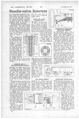
I N a conventional needle-valve injectiontion nozzle, the opening forces are always greater than those tending to close it, and according to patent No, 659,652, the reverse is desirable. An injector in which this condition is satisfied is shown in the patent by B. Bischof, Geneva, Switzerland.
The drawing shows the nozzle on an
enlarged scale. Fuel under pressure arrives via port 1 and enters a closed chamber (2), causing the main piston (3) to.descend. The motion compresses the fuel in space 4 and transfers some of it via a restricting port (5) into the
central b ore from which the output is taken.
The restricting port, is, however, dosed by the descending plunger and the fuel is compressed in the now completely c los e d chamber. The plunger ceases to descend when the outlets (6) emerge Irons their housing. On the return stroke, the spring force is considerably assisted by the elasticity of the trapped fuel and the combustion pressure acting on the exposed end of the plunger, and it is due to these factors that the high closing force is obtained.
STEERING HEAVY TRACTOR-TRAILER OUTFITS
PATENT No. 659,627 deals with the steering of heavy tractor-trailer combinations, particularly those having only two wheels on the tractor, such as are used for earth-scrapers. The patentee is the Caterpillar Tractor Company, San Leandro, California,
U.S.A. In the scheme proposed, the two vehicles are forcibly articulated one to the other by means of hydraulic rams.
The drawing shows a general layout, in which 1 is the tractor and 2 the trailer, the two being swivelled to a relative angle of 90 degrees. The straight-ahead position is indicated in
broken line. Both vehicles are fitted with a pair of hydraulic rams, as shown at 3, and they are all interconnected by a swinging lever (4)
which halves the steering angle. The steering wheel normally works a control valve, but will also operate directly should the power fail. The patent gives full details of all the various components and the fluid circuits employed.
One of the claims made for this system is that driver is able to "feel" his steering in a way which he cannot do with the normal twinor Si n gle -j a c k arrangement usually adapted.
BULK FUEL TANK CONSTRUCTION
TANKER vehicles, such as I used for the bulk transport of liquids, are usually divided into separate compartments so that partial emptying can be performed. With such
a vehicle, should the forward compartment be full when the rest is empty, steering becomes difficult on corners and there is a risk of overturning, due to the high location of the load. To overcome these troubles is the aim of a design shown in... patent No. 659,631, by Thompson Brothers (Bilston), Ltd., and H. Thompson, both of Bradley Engineering Works, Staffs. Instead of using a tilted parallel tank, a tapered one is used, as shown in the drawing. The top is horizontal and the sides are parallel, but the 'bottom slopes down to the rear. This shape permits of full gravity-assisted discharge and gives adequate clearance between the tractor and semi-trailer at the front end.
COIL SPRING DESIGN
PATENT NO. 659,645 comes from the Austin Motor Co., Ltd„ Birmingham, and shows improvements in the design of helical springs. By a progressive change of helix angle from ends to middle, it is claimed that it is possible to obtain uniform stress distribution in all the coils.
INDEPENDENT SUSPENSION WITH LEAF SPRINGS
A .SUSPENSION system using a Pt single transverse leaf-spring in conjunction with Parallel linkages, is shown in patent No. 658,880, by AJS StrOmmens Vaerksted, Oslo, Norway. Intended for use with front wheels, the scheme has no shackle-bolts and pins. The wheel is mounted on upper and lower links (1 and 2), the latter receiving the end of the spring on a special • type of bolt (3). The bolt has a Tshaped head, sunk in the lower link and resting in a concave seating, so that only a line contact is made. The spring-end is drilled, and is forged into a convex rib (4).
The rib seats in a concave slot formed across a thick washer, and here again, the proportions are such that only line contact is made, By adjusting the nut on the bolt, the effective height of the vehicle can be varied.
Such adjustment would also affect the spring loading which, in certain circumstances, might prove advantageous.
CRANKCASE VENTILATION
THE usual form of crankcase vernilaI tor is Somewhat haphazardly located, and in some circumstances the prevailing air-draught, instead of mildly sucking from the crankcase, may even blow into it. To make certain of the suction in all conditions of draught is the aim of an extractor device shown
• in patent No. 659,459, by the Fram Corporation, East Providence, Rhode Island, U.S.A.
The drawing shows a cross-section of the unit, which receives the crankcase ventilating pipe at its centre. The four external apertures are aerodynamically designed to create a suction whatever the direction of. the external air at re a m may be. The device has no moving parts.