


An Adjustable Cylinder-honing Tool
Page 48
If you've noticed an error in this article please click here to report it so we can fix it.
A Resume of Recently Published Patent Specifications Obtainable from the Patent Office, Price Is. Each
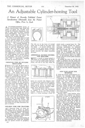
A CYLINDER-HONING device, of I-1 the abrasive-block type, forms the subject of patent No. 571,998, from George H. Alexander Machinery, Ltd., and E. Ball, both of 82-84, Coleshill Street, Birmingham. The patent is concerned mainly with the means for adjusting the working diameter.
Six stones (1) are used; these are held in metal channels which slide in radial grooves and are biased in an inward direction by means of a pair of spring rings (2). The working diameter is governed by a pair of cones (3 and 4); these are screwed right-hand and lefthand so that, by turning the central spindle, the stones are either forced outwards or permitted to retract, according to the direction of turning. The adjustment is made by a special key which engages the squared end (5) of the spindle. For ease of assembly and adjustment, the driving end is provided with a snap-action coupling operated by rotating sleeve 6.
IMPROVED TYPE OF DYNAMO REGULATOR
FROM C.A.V., Ltd., W. Bevis and A. Waters, all of Warple Way, London, W.3, comes, in patent No. 571,991, improvements in the design of regulators for the generators of motor
vehicles. The patent refers to the vibrating type as used in constant-voltage systems, although it may also be applied to constant-current circuits.
The regulator is, in this case, a dual unit and consists of a pair of coils (1), each of which is in series with one of the field windings of the generator. Each field circuit also includes a pair of vibrating points (2), across which is shunted a resistance. Although there are two sets of coils and points, there is but one magnetic circuit, consisting of the base, the cores and a bridge piece (3). The device acts in the wellunderstood manner; when the current in the coils reaches the maximum permissible value, the points are attracted by the cores and, by breaking, bring resistance into the field circuit. This immediately reduces the current, and the points meet again; thus is the vibratory action set up when maximum output is reached.
NON-SLIP TYRE FOR TRACTORS
AN improved form of tread for tractor tyres is shown in patent No. 572,048, by D. Kennedy, Harewood Forest, Longparish, Hants. The design reproduces, in rubber, a shape found to be highly satisfactory when formed in metal as a non-skid chain.
The drawing shows a cross-section of the proposed tyre, which has moulded ribs (1) spaced around its periphery. The ribs are in the form of twisted strips, and are made in one piece with the tread. A second scheme, also covered by the same patent, proposes the use of bonded-in inserts of some harder material, the shape remaining the same.
ADDITIONAL CLUTCH CONTROL FOR TRACTORS
WrLN a tracto.r is being backed to ple up an implement, the driver has to ,vork the clutch pedal with precision, and this is not easy when his
boots are covered with slippery mud To improve the control in such circumstances is the object of an additional hand control shown in patent No. 572,180, by R. Butcher, Stratton, Highfields, Great Dunmow, Essex.
The drawing shows the attachment as applied to a standard Fordson tractor. Bolted by two of the casing bolts is a frame carrying a lever (1) which works a second lever 12). The latter is hooked around the clutch operating mechanism, as indicated generally at 3, so that it pivots about the I edal spindle (4). A powerful spring (5), strong enough to hold the clutch out, is normally held out of action (as shown) by means of a toggle (6). In this position there is no interference with the normal pedal actuation of the clutch.
By pulling the lever to the left, die toggle is unlocked and the spring can, then hold the clutch in the free position. In addition to providing a delicate takeup control, the action is useful when it is desired to stop any machinery, driven from the take-off, without stopping the engine.
NEW LEAD ALLOY FOR BEARINGS LEAD has several goad features as a L—irnetal for bearings, chief among which, are its low friction and its good " wettability " by oil. It is also soft enough to flow from locally overloaded points and thus relieve dangerous stresses. Against this is its low strength and low fatigue resistance, and it is, therefore, usually alloyed with copper and other metals in order to improve matters. Patent No, 572,105, from W. Murray, New York, U.S.A., discloses a new scheme for utilizing lead by alloying it with indium.
Starting with a steel backing plate, the process first employs an electrodeposition of lead to an approximate depth of .015 in. It is then placed in a second plating bath and is given a thin facing with indium, the weight of which is about 3 per cent. of that of the lead. The third and final operation is that of diffusion; the bearing is heated to about 175 degrees C. for two hours, during which time the indium melts and soaks into the lead.
By carefully controlling the original dimensions of the steel shell and the depth of the deposits, the bearings can be finish-plated to the correct size, and thus sa final machining operation is obviated. The patent also describes an alternative scheme in which the bearings are hot-pressed from a mixture of lead and indium powders.