


HINTS ON. OVERHAULING.
Page 10
Page 11
Page 12
Page 13
If you've noticed an error in this article please click here to report it so we can fix it.
(3) The A.E.C. 4-ton Chassis. A Machine Designed for Simplicity and Accessibility. How to Dismantle It. What to Look for While Over
hauling Units.
THE A.E.C. chassis is admittedly one of the most simple chassis to maintain and overhaul. That it should be so is not surprising when one considers that its prototype was the B-type omnibus, which was, of course, designed with this end in view. Tlae•A.E.C. chassis naturally differs in many respects from the B-type, and incorporates.many improvements which render it eminently suitable for the uses to which a chassis intended solely for omnibus work could not satisfactorilysbe applied.
In the following notes we shall deal chiefly with hints on the complete overhaul of the A.E.C. chassis, but certain of the hints are also useful to persona engaged in making running or major repairs to a single unit. Whether dealing with a single unit or with the whole chassis, the first essential operation is thoroughly to clean such parts as will require to be removed. Particular care should be taken to clean dirt away from all nuts, bolts, bearings and any parts where joints will require to be broken.
We will presume that the body has been removed. To remove the engine, unship-the bonnet and radiator; providing an overhead hoist is available there is no need to remove the radiator guard, which is bolted to the side members, but 'if a floor crane, or " iron,man," as it is called, has to be employed it will be necessary to remove this. The engine is held down on its sub frame by four bolts which, of course, must be removed. The clutch coupling must be disconnected, and the starting handle bracket belts slacked off so that thin starting handle itself can be pulled up with its shaft at an angle. Next throw off all controls, and undo the exhaust connection. The engine ears then be slung out. of its sub-frame.
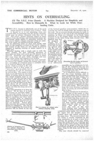
The next operation is to drop the gearbox. To do this, it is quite unnecessary to uncouple either of the universal joints, even if it be desired to remove the gearbox only without touching any other units. The gearbox must be supported underneath whilst the nuts and the three bolts which hold it in position are removed. Before doing this, however, the selector rod pins should be withdrawn. The nut for the bolt supporting the front of the gearbox will be found at the top assembly can be withdrawn by taking off the combined hub cap and driving dogs of the rear wheels and withdrawing the axle shafts. These are usually quite free.
It is sometimes found difficult to lift the worm housing, and to assist in breaking the joint between this and the rear axle casing, two setscrews are provided. Each of these is held in position by a lock nut, and to utilize them the lock nuts are slacked back and the. setscrews screwed in against the face of the axle easing. The nuts which keep the worm housing in position must, of course, be removed before this is done..
Trestles should now be placed under the rear of the frame, so that the weight of the frame is taken off the springs, and the latter removed if it is found that they require setting up or renewing in part or as a whole. The heavy volute springs will first require attention, and there are two ways of !removing these. The first is to remove the nuts of the four bolts holding each bracket ; the lower two bolts of 2,ae.lisean then be withdrawn quite easily, but to withdraw the upper two the bracket must be pressed down and pulled outwards at the same time. The second method—the one which is usually employed by the shop mechanies—is to put a. stout lever between the spokes of the rear wheel using the brake drum as a fulcrum/and wedge up the volute spring ; directly thin is lifted off its spigot on the top of the half-elliptic spring it can be slipped sideways, when it will drop out of the top bracket.
The rear wheels should be removed
next, and to do this it is necessary to jack up the axle. The combined hub caps and driving dogs have already been removed, and to remove each wheel it is only necessary to unscrew and remove the retaining nut locking bolts and then unscrew the wheel retaining nut itself. The rear wheel complete with its roller bearings can then be removed. If anydifficulty is experienced in withdrawing the rear wheels it may possibly be due to flanges having formed on the brake drums owing to these being badly worn; the brake shoes being adjusted up to operate in the worn parts of the drums, the flanges butt up against these, and it will be found necessary to slack off the rear brake rods, or remove the brake lever pins. To remove the rear springs, first remove the spring retaining bolts, then take out the bolt at the front end of each spring and lift the frame or drop the rear axle until the latter is clear of. the tongues and nipple on the bottom leaf. Each spring can then be drawn forward so that the rear shackle bolt can be removed.
To remove the steering g e air first remove the steering wheel, throw ofithe magneto control connection, drop the steering rod, disconnect the steering column plate from the footboard, release the clip bolt at the top of the steering box and withdraw the steering tube upwards, then by removing the four bolts holding the steering box to the side-member the former can be entirely removed by lowering to the ground and drawing from under the chassis.
The change speed control very seldom requires touching unless the barrel shaped swivel bushes are worn. If this is so they can be replaced without any difficulty. The front axle with its. wheels is usually left until last, as it is safer to let the front portion of the chassis remain supported by the wheels so long as possible.
In some cases it is required to remove the lower half of the crankcase without removing the whale engine. In the old type vehicles turned out during the war this is a, little difficult, and it is necessary to undo the engine holding. down bolts and to jack up the engine about 2 ins by means of a jack under the flywheel. The steering tie rod must also be disconnected at one end and swung out of the way. It is not necessary to disconnect any controls or break water joints, the sole object being to allow the lower half of the crankcase to clear the rear engine cress-member.
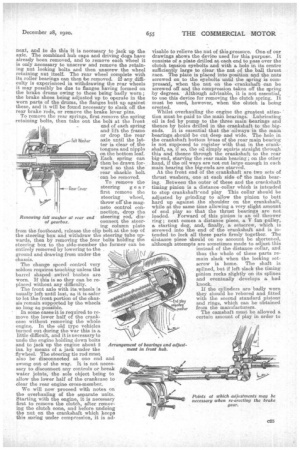
We will now proceed with notes on the overhauling of the separate units. Starting with the engine it is necessary first to remove the clutch, after removing the clutch cone, and before undoing the nut on the crankshaft which keeps this spring under compression, it is ad
Renewing felt washer at rear end of gearbox. visable to relieve the nut of this pressure. One of our drawings shows the device used for this purpose. It consists of a plate drilled at each end to pass over the clutch tension eyebolts and with a hole in its centre sufficiently large to clear, the nut of the ball thrust race. The plate is placed into position and the nuts screwed on to the eyebolts until the spring is compressed, when the nut on the crankshaft can be screwed off and the compression taken off the spring by degrees. Although advisable, it is not essential, to use this device for removing the clutch spring. It must be used, however, when the clutch is being erected.
Whilst overhauling the engine the greatest attention must be paid to the main bearings. Lubricating oil is fed by pump to the three main bearings and thence by holes drilled in the crankshaft to the bigends. It is essential that the oilways in the main bearings .should be cut deep and wide. The hole in the crankshaft bottom brass of the rear main bearing is not supposed to register with that in. the crankshaft, as, if so, the oil Simply squirts straight through this and thence through the crankshaft to the rear big-end, starving the rear main bearing; on the other hand, if the oil ways are not cut large enough in each main bearing the big-ends are starved. At the front end of the crankshaft are two sets of thrust washers, one at each side. of' the main bearing. Between the outer of these and the crankshaft timing pinion is a distancecollar which is inteuded to stop crankshaft endplay This collar 'should be adjusted by grinding to allow the pinion to butt hard up against the shoulder on the crankshaft, while at the same time allowing a very slight amount of end play so that the thrust bearings are not loaded. Forward of this pinion is an oil thrower ring ; next comes a distance piece, a V fan pulley, a starting dog, and, finally, a setscrew, which is serewed into the end of the crankshaft and is intended to lock all these parts firmly together. The distance piece should on no account be shortened, although attempts are sometimes made to adjust this instead of the distance collar, and thus the whole of these parts remain sleek when the locking setscrew is home. The shaft is splined, but if left slack the timing pinion rocks slightly on its splines and eventually develops a bad knock.
If the cylinders are badly worn they should be rebored and fitted with the. second standard pistons and rings, which can be obtained from the manufacturers.
The camshaft must be allowed a certain amount of play in order to permit the half-compression cams to be brought into action when desired, but it is held in, its normal position by a strong spiral spring inserted between a ball thrust washer and the camshaft timing wheel. The thrust washer takes up the spring thrust. A certain amount of wear occurs on the intermediate timing wheel spigot pin, and if this is worn oval it must be renewed. The intermediate timing wheel is constructed of phosphor bronze and is fitted with a pressed-in bush, which can easily be screwed.
The clearance between the valves and tappets must be .006 in.
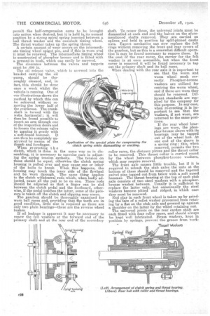
The oil release valve,. which is screwed into the bracket carrying the oil pump, should be thoroughly cleaned, and, in fact, this should be done once a week whilst the vehicle is running. One of our illustrations shows the method by which this can be achieved without removing the lower half of the crankcase. The crankshaft is turned with the webs horizontal ; it will then be found possible to insert an arm through one of the inspection doors and to loosen the release valve by tapping it gently with a soft-nosed hammer. It can then be completely unscrewed by means of the thumb and forefinger. When re-erecting t h clutch, which is done in the same way as in dissembling, it is necessary to exercise care in adjust ing the spring tension eyebolts. The tension on these should be equal, otherwise the clutch spring housing is pulled over and may cause one or other of the bolts to break. When this happens, the housing may touch the inner side of the flywheel and be worn through. The same thing applies to the clutch withdrawal rods which, when badly adjusted, cause all the pull to be on one. These rods should be adjusted so that a finger can be slid between the clutch pedal and the footboard, otherwise, if the pedal touches the latter, some of the pressure is taken off the clutch and slipping may ensue. The gearbox should be thoroughly examined for worn ball races and, providing that the teeth are in good condition, little else is required as there are only two plain bearings—these are the reverse wheel bushes.
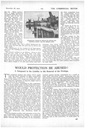
If oil leakage is apparent it may 'be necessary to renew the felt washers at the forward end of the primary shaft and at the rear end of the secondary shaft. To renew these, the universal joints must be dismantled at each end and the halves on the aforementioned shafts removed. They are carried on splines and held in position by split-pinned castle nuts. Expert mechanics can now replace the felt rings without removing the front and rear covers of the gearbox, but as this is a, somewhat difficult operation it may be found necessary to remove these. In the ease of the rear cover, the carrier for the felt washer is at once accessible, but when the front cover is removed it will be found necessary to tap out the primary shaft and its ball races. When dealing with the rear axle it is important to see that the worm and worm wheel mesh correctly. Phosphor-bronze washers are utilized for centring the worm wheel, and if these are worn they should be renewed. Different standards are supplied by the company for this purpose. In any case, when re-erecting it, is important to see that the washers, if not worn, are returned to the same positions.
If the rear wheel bearings are worn, the phosphor-bronze sleeve with its bearings may be tapped out of the wheel hub. At one end of the sleeve is a spring ring ; this, when removed, permits the two roller races, the distance pieces and the thrust collar to be removed. This thrust collar is carried round by the wheel between phosphor-bronze washers, which may require renewal. The front axle causes little trouble, but if it is required to rebush the stub axles the nuts at the bottom of these should be removed and the tapered swivel pins tapped out from below with a soft nosed hammer. The thrust bearing at the top of each stub axle consists of two steel washers with a phosphorbronze washer between. Usually it is sufficient to replace the latter only, but occasionally the steel washers become pitted and ridged, M which case they must be renewed. End play in each front wheel is taken up by grinding the face of a collet washer prevented from rotating by a flat on the stub axle and pressed up against a shoulder on the latter by the wheel retaining nut. The universal joints on the rear cardan shaft are each fitted with four roller races, and should always be kept well lubricated. iBrass washers, kept in position by springs, prevent, the grease from work lag out. These washers have a slight oscillating movement when the joints revolve, and, if run dry for long periods, may break up, the pieces working into the ball races causing some damage. Par ti cular attention should always be paid to the brakes, If the drums are badly worn, the shoes can be built up by inserting packing pieces between the hardened cam plates and the shees.
Sometimes the brake shoe fulcrum pins, which may require renewing, are so rusted into position as to be difficult to remove. If, however, a nut is inserted between the inner end of each pin and the top of the spring clip, and a chisel hammered between eaCh nut and clip, the pins can be driven Out quite easily. The adjustment of the brakes is of importance, otherwise the braking power of the wheels will be unequal.
The correct method is as follows: Remove pins from the rear ends of the long rods with turnbuckles, also the rear pins from the two rear brake rods on off side of chassis. Adjust set-screws until brake shoes just clear drums. Adjustlength of near side rear brake rods until levers on compensating shafts haveaan inclination to the rear of 20 degrees Then adjust length of off side rear brake rods until the links suspended from the compensating levers are vertical, and the pins will pass through the rods and brake levers on rear axle. Adjust length of the rods carrying turnbuckles until they will couple up with the vertical links.
No lining up of the engine and gearbox is required, as the frame and units are drilled to jig in the first place and the long double-jointed clutch shaft compensates for slight errors.
If play occurs in the steering gear, the method of adjustment is to take out the bottom cap and insert packing washers to take up wear on the thrust bearings, care being taken that, with the new washers in position, the bottom cap tan be tightened right home without binding the thrust races. Occasionally the springs in the steering tie rod ball joints break these must be replaced; • the casehardened steel. cups may also be found to be chipped. We have not yet dealt with the frame. If it is found that the rivets used in the engine sub-frame are loose, it is advisable to knock these out, learner out the holes, and replace by fitted baits. The front brackets of the rear springs take all the drive when the chassis is in motion. It is therefore important that the bolts holding these brackets be kept tight.