


Patents Completed.
Page 20
If you've noticed an error in this article please click here to report it so we can fix it.
Complete specifications of the following patents will be sent to any address in the United Kingdom upon receipt of eightpence per copy at the Sale Branch, Patent Office, Holborn, W.C.
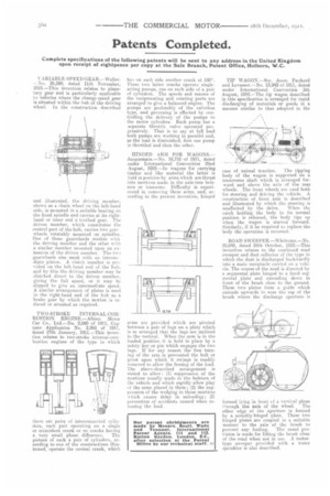
VARIABLE SPEED GEAR.—Weller. —Nu. 26,290, dated 11th November, 1910.—This invention relates to planetary gear and is particularly applicable to vehicles where the change-speed gear is situated within the hub of the driving wheel. In the construction described and illustrated, the driving member, shown as a chain wheel on the left-hand side, is mounted in a suitable bearing on the fixed spindle and carries at its righthand or inner end a toothed gear. The driven member, which constitutes the central part of the hub, carries two gearwheels rotatably mounted on spindles. One of these gearwheels meshes with the driving member and the other with a similar member mounted upon an extension of the driven member. The twe gearwheels also mesh with an intermediate pinion. A clutch member is provided on the left-hand end of the hub, and by this the driving member may be clutched direct to the driven member, giving the full speed, or it may be slipped to give an intermediate speed. A similar arrangement of plates is used in the right-hand end of the hub as a brake gear by which the motion is reduced or arrested as required.
TWO-STROKE INTERNAL-COMBUSTION ENGINE.—Alhion Motor Car Co., Ltd.—No. 2,060 of 1911, Cognate Application No. 2,068 of 1911, dated 27th January, 1911.—This invention relates to two-stroke internal-combustion engines of the type in which there are pairs of interconnected cylinders, each pair operating on a single or coincident crank or on cranks having a very small phase difference. The pistons of such a pair of cylinders, according to one of the constructions illustrated, operate the central crank, which
has on each side another crank at 1800. These two latter cranks operate singleacting pumps, one on each side of a pair of cylinders. The speeds and masses of the reciprocating and rotating parts are arranged to give a balanced engine. The pumps are preferably of the valveless type, and governing is effected by controlling the delivery of the pumps to the motor cylinders. Each pump has a separate -throttle valve operated progressively. That is to say at full load both pumps are working in parallel and, as the load is diminished, first one pump is throttled and then the other.
HINGED ARM FOR WAGONS.— Jacquemain.—No. 18,710 of 1911, dated under Iuternational Convention 22nd August, 1910.—In wagons for carrying Limber and like material the latter is held in position by arms which are thrust into mortices made in the axle-tree bolsters or transoms. Difficulty is experienced in removing these arms, and, according to the present invention, hinged
arms are provided which are pivoted between a pair of lugs on a plate which is so arranged that the lugs are inclined to the vertical. When the arm is in the loaded position it is held in place by a safety key or pin which engages the two lugs.. If for any reason the free turning of the arm is prevented the bolt or pivot upon which it swings is readily removed to allow the freeing of the load. The above-described arrangement is stated to allow : (1) suppression of the mortices usually made in the bolsters of the vehicle and which rapidly allow play of the arms placed in them; (2) the suppression of the wedging in these mortices which causes delay In unloading; (3) prevention of accidents caused when releasing the load.
TIP WAGON.—Soc. Anon. Panhard and Levassor.—No. 13,942 of 1911, dated under International Convention 5th August, 1910.—The tip wagon described in this specification is arranged for rapid discharging of materials or goods in a manner similar to that adopted in the case of animal traction. The tipping body of the wagon is supported on a transverse shaft which is arranged forward and above the axle of the rear wheels. The front wheels are used both for steering arid driving the vehicle. A construction of front axle is described and illustrated by which the steering is unaffected by the drive. When the catch holding the body in its normal position is released, the body tips up when the wagon is started forward. Similarly, if it be required to replace the body the operation is reversed.
ROAD SWEEPER.—Whittome.—No. 25,019, dated 28th October, 1910.—This invention relates to the combined road sweeper and dust collector of the type in which the dust. is discharged backwardly into a main receptacle carried on a vehicle. The course of the mud is directed by a segmental plate hinged to a fixed segmental plate and extending down in front of the brush close to the ground. These two plates form a guide which extends upwards to near the top of the brush where the discharge aperture is formed lying in front of a vertical plane
through the axis of the wheel. The other edge of the aperture is formed by a suitably-hinged plate. These two hinged plates are coupled in a suitable manner to the axle of the brush to prevent any fouling. The usual provision is made for lifting the brush clear of the road when not in use. A motortype sweeper provided with a water sprinkler is also described.