


Rail-guided Road Vehicle
Page 80
If you've noticed an error in this article please click here to report it so we can fix it.
SOME years ago a British manufacturer patented a system for using road vehicles in long trains which were guided by a single central rail controlling the steering mechanism. The scheme was intended as an inexpensive substitute for a railway system over rough terrain. Further suggestions in this respect now
• appear in patent No. 812,281. (G. Ciocca and Tranviaria Municipale, Foro Buonaparte 61, Milan, Italy.) The drawing shows a plan of the tractive unit employed; the trailer would be attached to this via a king-pin pivoting in the socket (1). Each wheel is powered separately by an engine (2) driving via a gearbox (3), propeller-shaft (4) and final bevel drive (5).
The 'centralguide-rail (not shown) engages with concave rollers (6) mounted on sprung arms. If the rollers are displaced sideways by the rail, they move the track-rod (7) via levers (8) and so actuate the steering to keep the roadwheels parallel to the rail.
A middle wheel (9) does not normally make contact with the rail, but if it should do so it warns the driver that something is amiss such as a puncture or incorrect steering.
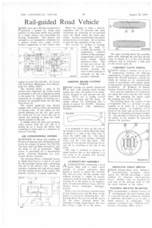
AIR CONDITIONING SYSTEM
I NTENDED for buses and coaches, an improved heating and ventilating system forms the subject of patent No. 812,776. The fans used can blow warmed air into the body or act as extractors. Their action is controlled by a thermostatic device. (Clayton Dewandre Co., Ltd., Titanic Works, Lincoln.)
The drawing shows a schematic layout in which three fans (1, 2 and 3) are used for the passenger spaces, plus a demisting unit (4) in the driver's cab. Each fan contains a heating unit and all etre piped into the cooling system of the engine. The demister, however, is piped separately. When the engine is cold, a thermoresponsive unit (5) prevents the main circulation by actuating an air-operated valve (6) which closes the main pipe circuit. In these circumstances the heater system works as a by-pass. Air or suction is used for the operation of the valve.
The reversal of air-flow is brought about by using reversible fan motors. A temperature sensitive bellows in the passenger compartment controls a micro switch which operates a relay. This in turn can reverse the direction of armature current, -causing the fans to blow inwards or outwards as the temperature demands.
KEEPING BRAKE FACINGS CLEAN
BRAKE facings are usually chamfered on their ends causing small foreign bodies that enter the drums to be immediately dragged in and pressed into the lining. Water too is readily carried between the facing and the drum. A simple scheme for eliminating this is shown in patent No. 812,993. (Svenska Bromsbandfabriken A.B., Molnlycke, Sweden.)
It is proposed to turn up the end of the lining to form a sharp chisel-like edge as shown at 1, and at the same time to bevel the under edge (2). The sharp edge is said to act as a scraper, removing water and dirt from the drum. The amount of turn up may be between .01 in. and .04 in. according to the size of the drum.
The edge is claimed to preserve its shape because due to the undercut it is too weak to be pressed into wearing contact with the drum.
GUDGEON-PIN ASSEMBLY
/X GUDGEON-PIN comprising a hard PA sleeve filled with a softer metal capable of greater expansion when heated is shown in patent No. 812,030. The soft core may rub the cylinder wall without harming it, whilst its greater expansion tends to keep the sleeve a good working fit in the piston at all temperatures. (Continental Motors Corp., 205-215 Market Street, Muskegon. Michigan, U.S.A.)
Such a core can, however, become loose at low temperatures and the basis of the patent is a means for obviating this. The drawing shows the core (I) and the sleeve (2); the lower drawing shows the assembly at high temperatures, the core then being a tight fit in the sleeve.
The upper drawing shows the assembly when cold; although the core has shrunk away, as shown at 3, it has also shrunk endways, and so maintains a tight grip on the conical ends (4).
VARIABLE VALVE TIMING
VALVE timing is usually set to be a compromise between the differing requirements of high and low speeds but patent No 812.303 discloses a scheme by which the timing can be automatically varied in accordance with engine speed, so that greater overlap is obtained at high revolutions, (F. Waldron, 34 Albany Avenue, Eccicston Park, Prescot, Lancs.)
Two separate camshafts are employed, one opens the valves and the other closes them. By changing the phase angle the opening time can be varied.
The drawing shows the essence of the arrangement; this is a sprocket or gear coupled to its shaft by a centrifugal advancing device. A baekplate ( I) is keyed to the shaft and carries pivots (2). On these are mounted centrifugal weights (3). The sprocket is driven by pivot pins (4) which, as the weights fly outwards advance the sprocket.
SILENCING CHAIN DRIVES
FROM Daimler-Benz A.G., StuttgartUntertiirkheirn, Germany, comes patent No, 814.268 describing a novel method of silencing chain-sprocket drives. Rubber rings are mounted on each side of the sprocket teeth so that the chain bottoms on the rubber.
FLEXIBLE BIG-END BEARINGS
Taccommodate a limited amount of I misalignment, the steel backing shell of a big-end bearing is grooved, indented or otherwise deformed so as to give a small measure of cushioning. The patentee is Clevite Corp., 17000 St. Clair Avenue, Cleveland, Ohio, U.S.A.