


A Vehicle-borne Fuel-cracking Plant
Page 60
If you've noticed an error in this article please click here to report it so we can fix it.
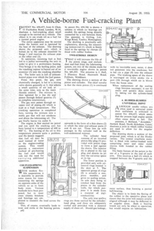
DATENT No. 694,457, from S. Chan, I 53 Fairholme Road, London, W.14, discloses a fuel-cracking plant small enough to be carried on a vehicle. The object i to use crude oil as a fuel for a normal petrol engine.
The entire apparatus may be carried under the bonnet and is operated' by the heat of the exhaust. The drawing shows ,,the proposed unit, 'which is bolted on to the exhaust manifold by flange 1 and receives the exhaust pipe at the other end (2).
In operation, incoming fuel is first fed to a. jacket surrounding the unit in order to give it a preliminary heating. This brings it to the boiling point, and the resulting vapour is forced out of an atomizer (3). into the cracking chamber (4). The latter unit is full. of exhaustheated pipes over Which the fuel passes.
'From this point, the gas', now chemically changed, is led to a mixing valve shown generally at 5; this admits a small quantity of air and, at the same time, acts as the main throttle control. The mixture is. then agitated by a fan (6) and passes ,through helical grooves (7) to complete intermixture.
The gas next passes through an upper coil of piping (8) which is kept at .a high temperature. The cracking operation is completed here, turning the mixture into a stable, gas that will not condense and dilute the lubricating oil. The gas finally leaves via outlet The engine is first started On petrol and run until the cracking unit has been heated to a temperature of 600 to 900° C. The heating of the oil to this temperature presents quite a problem, and the 'patent suggests that fuel. oil may be used instead of water in the engine-cooling system. This would provide a convenient method of pre-heating the fuel and would rule out the need for carrying additional apparatus.
COUPLED-SPRING SUSPENSION WITH modern flexVV ible suspensions it is desirable to provide some means for interconnecting the springs on opposite sides of the vehicle so as to limit body sway. Various methods have been proposed, but in most cases chassis brackets and bearings are ern played to transmit the load across the frame.
This, of course, eventually leads to wear and rattle at the bearing points. A42 In patent -No. 694,386 is shown a scheme in which no bearings are needed, the springs being directly connected by a rod between them. The patentee is Girling, Ltd., Kings Road, Tyseley, Birmingham.
The drawing is practically selfexplanatory, showing the connecting torsion-rod (1) which is -firmly fixed to' the springs by clamps (2) fitted with rubber bushes.
TWO-STROKE DESIGN
THAT it will increase the life of the piston rings,, and exclude, dust and fuel from the lubricating system, are two Of the claims made for a two-stroke engine shown in patent No, 081,203. The patentee is J. Hall, 3 Florence Road, Hanworth Road, Feltham, Middlesex.
The drawing shows a section of the piston and cylinder, The chief novelty is that the main piston (1) is continued upwards in the form of a thin sleeve (2) in which the inlet and exhaust ports (3 and 4) are cut. These line up with passages in the cylinder wall in the well-understood manner.
The cylinder head consists of an inverted piston-like plug (5) provided with piston rings to form a seal against the sleeve. The injector (6) is placed in the top plug and directs its jet into the cut-away space at its tip.
The lower portion is provided only with oilcontrol rings located :n the skirt at 7. The apparent group of rings (8) is actually a onepiece member, and gives no sealing action, its sole duty being to conduct heat from the piston to the cylinder walls, for which purpose it is made from a material of nigia conductivity.
The only true sealing rings are those carried by the cylinderhead plug, and these are adequately cooled and provided with a metered supply of clean oil. Should gas leakage,.
with its inevitable soot; occur, it does 'not penetrate into the crankcase, but is led via a pipe (9) into the exhaust pipe. The working space of the sleeve is scavenged on -every stroke via a port (10) through which air is blown from the boost inlet.
When replacement of the sealing rings becomes necessary, it can be easily and quickly done merely . by taking out the cylinder-head plug, A RUBBER-BUSHED UNIVERSAL JOINT
A LHOUGH needlerollers. are I"%. often used in universal joints their usefulness is criticized in patent No. 694,437, which states that the present high engine speeds often cause them to fail. The' patentee, J. Holland, "Avondale," 'Newark Road, North Hykeham, Lanes: discloses a joint in which rubber bushes are used to allow for the angular deflection.
The drawing shows a section of the proposed joint, which is of the Hooke variety. The central cruciform member is fitted with rubber-bushed units comprising inner and outer metal sleeves both bonded to the rubber filling.
The basic feature of the patent is the use of a V-groove in the end of each arm. This receives a ball (1) which is trapped between the V-groove and the outer surface, thus forming a partial ball-bearing.
The object is to limit the flexing of the rubber to the operative plane and ensure that the joint will remain axially aligned although it may be deflected in an angular sense. Such a bearing would not only be silent in operation, but would require no lubrication.