A NEW• ARTICULATED SIX-WHEELER.
Page 32

If you've noticed an error in this article please click here to report it so we can fix it.
A Rdsumd of Recently Published Patent Specifications.
I&
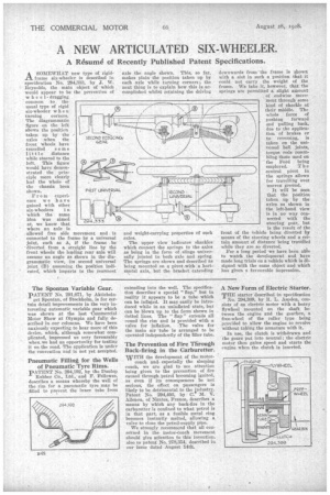
A SOMEWHAT new type of rigid frame six-wheeler is described in specification No. 294,333, by J. W. Reynolds, the main object of which would appear to be the prevention of wheeldragging common to the usual type of rigid six-wheeler when turning corners. The diagrammatic figure on the left shows the position taken up by the axles when the front wheels have travelled some little distance while steered to the left. This figure would have demonstrated the principle more clearly had the whole of the chassis been shown.
From experience we have gained with other six-wheelers i n which the same idea was aimed at, we know that where an axle Is allowed free side movement and is connected to the frame by a universal joint, such as A, if the frame -be • diverted from a straight line by the front wheels the leading rear axle will assume an angle as shown in the diagrammatic view, its second universal joint (B) assuming the position indicated, which imparts to the rearmost axle the angle shown. This, so far, makes plain the position taken up by each axle while turning corners ; the next thing is to explain how this is accomplished whilst retaining the driving and weight-carrying properties of such axles.
The upper view indicates shackles which connect the springs to the axles as being in the form of . slings universally jointed to both axle and spring. The springs are shown and described as being mounted on a pivot with a horiziKntal axis, but the bracket extending downwards from the frame is shown with a slot in such a position that it could not carry the weight of the frame. We take it, however, that the springs are permitted a slight amount . of endwise movement through some kind of shackle at their middle. The whole force of pushing forward and pulling back. due to the application of brakes or to reversing, is taken on the universal ball joints, torque rods resembling those used on the Ford being employed. The central pivot in the springs allows for travelling over uneven groUnd.
It will be seen that the position taken up by the axles as shown in the left-hand view is in no way connected with the steering gear, but is the 'result of the front of the veh'de being diverted by means of the steering wheels and a certain amount of distance being travelled while they are so diverted.
For a long period we have been able to watch the development and have made long trials on a vehicle which is designed with the same object and which has given a favourable impression.


