


RUNNING, UPKEEP AND OVERHAUL.
Page 31
If you've noticed an error in this article please click here to report it so we can fix it.
Interesting Contributions from Maintenance Engineers, Drivers and Mechanics.
An Engine-testing Device.
ONE of our correspondents, " of Barnsbury, N., sends us an example of a device he has made for testing the firing of multi-cylindered engines. Ile points outthat the method usually employed of cutting out one cylinder to test the evenness of firing is practically of no value, as there are still three cylinders firing.
His device cuts out all cylinders but one, and as the cutting out can be accomplished so quickly and all cylinders made to fire again there is practically no risk of the engine stopping. The device consists of a plate of vulcanite, through which passes a spindle carrying a star-shaped piece divided as if there were to be five equally spaced arms, of which one has been cut away. This star piece is in contact with the central spindle, which carries an insulated knob at one end and an earth wire at the other end. The disc of vulcanite is divided into five even spaces, but only four contact points are introduced, one space being left blank.
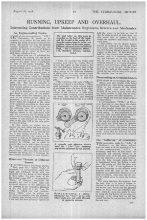
A wire is attached to the earth pole and fixed to any part of the engine. Four other wires are attached, one to each of the contact points, which are numbered 1, 2, 3, and 4 respectively. The wires are attached to the plugs of the cylinders according to their numbers. When the star is set as shown in the left-hand view, all cylinders will fire as usual, but when moved to the position shown in the right-hand view only No. 1 cylinder will be firing, as all others will be earthed, so that whichever number is not covered by one of the arms of the star will be the only cylinder that is firing.
By this means an engine can be started up, and, when hot and running well, all but No. 1 cylinder can he esrthed, then all but No. 2, next all but No. 3, and, finally, all but No. 4. Between these positions the engine can be allowed to pick up by placing the arms between the contacts. The change from cylinder to cylinder can be Tade so rapidly that one is able to bear in mind the exact note of each cylinder and its effect in driving the engine with only one cylinder. Not only does this device indicate the firing, but it indicates the even supply of mixture to each cylinder.
Wheel-nut Threads of Different Senses.
" I NOTICE that in your issue of June 19th, page 623," writes " C.J.," nf Bradford. "a correspondent asked why right and left-hand thread nuts are employed for the fixing of disc wheels to their hubs. In your issue of the 7th instant, page 857, a correspondent, Shim,' of Glasgow, attributes the necessity for nuts to have right and left-hand threads to the difference of, air pressure at the respective distances of the two sides of a nut from the centre on which the hub revolves. Surely Shim ' must be pulling our leg when he suggests that air pressure, no matter how strong, could blow loose a nut that had been properly tightened?
"When we consider the slight total pressure and when we realize that it is not the whole of this pressure, but only the difference between that acting on one side of the nut and that on the other, owing to the different distances of these sides from the centre around which they are revolving, one can only take the suggestion as a first-class joke.
"The real reason why nuts of different threads are fitted is as follows :—There must necessarily be some minute degree of slackness where the bore of the wheel fits on the spigot of the hub. The weight of the vehicle as it rolls along causes a slight creeping action between the wheel and the huh, this creeping action is transmitted to the nuts which hold the wheel to its hub, so that if _ they be right handed on both sides, one side would tend to tighten all nuts, whilst the opposite side would tend to undo them.
"The action can be clearly demonstrated by holding a nut down firmly on a table, then inserting a bolt in the nut, first having placed a loosely fitting washer on the bolt. If this washer be held by the fingers and moved' in a circular path in a clockwise direction, but not revolved on its own axis, it will be seen that the bolt is slowly creeping around in a reverse direction, namely, anti-clockwise, which will tend to screw it out of its nut. If the direction of the path of the washer be reversed the bolt will be seen to be gradually creeping into its nut."
Dismantling an Overland Clutch.
THE clutch of the Overland, like many others, may give trouble while being dismantled and when being reassembled, owing to the pressure of the clutch spring, which may cause the last threads of the nuts to strip while they are being undone. It will also be found difficult to press the two members to. gether while the nuts are being located on their studs.
• A correspondent, " T.H.," of "Myers ston, has had to take down the clutch of a 23-ewt. Overland, 1926 type, and had some trouble fixing up the clutch owing to the difficulty of compressing tho clutch spring. It was impossible to get the fin, nuts into their places owing to the strength of the clutch spring.
After trying several methods, includin the use of a jack, he made two extralong studs and fitted them in opposite sides of the clutch. By the aid of these he was able to bring the halves together so that all nuts could be placed on. their studs. After this he removed the long studs and replaced them by the original ones.
The " Collaring " of Crankpins.
THE suggestion made by " A.B.," of
Stockport, on the above subject does not meet with the approval of two of our correspondents. " C.T.Y.," of Peckham, says that he has found the diagonally cut channel, which is so generally used, to be the best, provided that the channel is cut so that it intersects the hole through which the oil is introduced from the hollow crankpin. Ile points out that the plan suggested by " A.B." is not applicable to the main bearings, as the channel must coincide with the hole in the crankshaft for an appreciable distance during each revolution, otherwise the oil cannot be relied upon to enter the hollow crank.
For main bearings, he suggests that the best plan is to turn a recess or channel in the top half only, so leaving the bottom half, which has the greatest stress to bear, with an unbroken surface. This, he says, can easily be done by using the top halves of two separate bearings, or by using half an old discarded bearing in conjunction with half the new one.