


IMPROVING THE GOODYEAR SIX-WHEELER.
Page 28
If you've noticed an error in this article please click here to report it so we can fix it.
A Résumé of Recently Published Patents.
THE GOODYEAR Tyre and Rubber Co., deal, in a couple of specifications, with, interesting modifications M the design of the six-wheeled chassis which was described in The Commercial Motor for June 12th last; One specification describes improvements in • the method of transferring the drive to the chassis; the other is concerned -with electric transmissien.
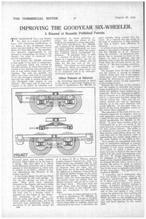
In the former,. No. 193,427, reference is first made to one form of torque-reaction mechanism which was covered by the older patent, in which the' torque reactions of two driving axles are met by a pair of rods which couple the two axles together. The rods are parallel, one above the other, and each is connected to its axle through a vertical pivot, thus allowing the axles a certain amount of side movement with respect to one another. The other end of each rod is coupled to its fellow by shackles and
universal joints, and by some resilient material, either rubber, or in the form of a spring. The total effect is to afford shock-absorbing properties and a certain • aniount of free movement to either axle in relation to its fellow, without in any way diminishing the efficiency of the torque reactions.
In the former design the driving thrust was sustained by the road springs. In. this one the springs are free at. their ends. They pivot upon trunnions mounted in the chassie; and rest in slides on the axles. The driving thrust is carried by radius rods. One rod couples the two axles together; the other couples the front axle to a bracket which is mounted on the frame of the chassis. The connections in all cases,i.e., between axles and radius rods, and between radius reds and frame, are of the universal type, permitting freedom of movement in all directions except the longitudinal, in which direction' of course, the pull. and thrust of the braking and propulsive forces take place. The other specifiention2 No. 193,428, also commences by describing the form of torque •reaction mechanism we have just described, and to which the patentees evidently attach considerable im
portance. It proceeds, then, to refer to a method of driving each axle by means of a separate motor, one for, the front axle and its two wheels, and the other for the rear axle of the two behind. The motors are each suspended in trunnions, which are carried by the chassis frame, and the drive from each to its respective axle ii by telescopic universally jointed shafts.
Other Patents of Interest.
. An interesting improvement in detail in the design of rear-wheel brakes is described in specification No. 200,742, by G. J. Shave, 0. W. J. Watson, and the London General Cmnibus so., Ltd; Two brake drums are mounted Side by side upon the wheel. One is somewhat sinaller in diameter than the other, but the brake shoes are of the same dimensions, the difference in diameter being made up by utilizing thicker linings on the shoes for the larger drums. 'When the linings become worn, the shoes operating within the smaller drum are relied with the thicker material, and are set to work in the larger drum. The shoes from the larger drum, with the linings, presuniably, worn down to the requisite thinness, are transferred • to the smaller drum.
A novel type of steam generator is described in specification No. 200,646, by F. Van Canegherri. It is gas or oil fired, and the burning gases are compelled to travel along tubes or conduith, tvtich are submerged in the water in the boiler, the
gases actually, being turned into the water. It is claimed that, the whole of the heat of combustion is thus utilized, and that a higher heat efficiency is
obtained. , .
A system of air-cooling for e, motorcar engine is the subject'of patent specification No 195,036, A. A. H. TiSserant being the inventor.A. substantial belt. driven fan is mounted in front • of the engine, in such a position; says the patentee, that it has the advantage, derived from the forward motion of the vehicle, of "the best working conditions, especially as regards the • power absorbed."
The draught from the fan is divided and the current is carried in suitable conduits along each side of the engine, where, again, each current is further subdivided by intercepting , vanes so that each cylinder secures its due proportion of the cooling stream.
Vertical fins are cast on the cylinder and the engine is enclosed, the casing being completed by a cover on the top, which has 'guiding vanes formed on its underside, which are designed to deflect the air currents on to the cylinder heads and in a downward direction along the vertical cooling line. This says the inventor, ensures the cold air impinging directly on to the valve chambers an avoids eddying. At the same time, removal of the cover facilitates access to the valves when required.
The amenities of the road will be considerably improved, -we imagine, when at each important junction there is erected a pillar of the type which is described in patent specification No: 200,644, by H. Booth. A neat ferro-conerete pillar is surmounted by a box or casing of the same material, which serves as a support for four, convex mirrors. The pillar is so disposed at cross-roads; for example, that.anyone approaching along any one road may 'see, in the mirrors, what is approaching the .corner, along either of the roads leading, to the right or left.
Most people are acquainted with that form of mechanism designed to convert the reciprocating motion '(of a piston, for example) to the rotary .movement (say, of a crank); in which a block with a transverse slot is fixed to the end of-the piston rod, the crank pin engaging. with the slot. H. Briggs improves on this, for purposes of its application to the needs of the internal-combustion engine, by forming the slot with a curve in it, so causing the piston to dwell at certa;.n points in the' stroke. Improved operationof the motor is claimed as the result of this innovation. The specification is numbered 200,704. • A connecting rod is eliminated, also, from the design of engine which is described in specification No.200,620, be G. S. Dawe and another. The cycle is two-stroke, and the operation is doubleacting. A separate charging cylinder is utilized, the piston for which is on the same rod as the power piston. The lower end of this rod carries a cam, which rotates the piston rod, thus euabling the charging piston to act also as a val,ve. There are teeth on the periphery of the cam which transmit. the power through spur and bevel -.•gearing to the engine shaft.