


EQUIPPING A COACH FOR WIRELESS RECEPTION.
Page 13
Page 14
If you've noticed an error in this article please click here to report it so we can fix it.
That Desirable Property of the Thermionic Valve, whereby it may be Retro-actively Coupled so as to Increase its Sensitivity is Fully Described in this Article in its Application to the Three-valve Receiver Already Outlined.
INT THE last few articles, appearing under this heading, we have successively built up a threevalve receiver. We dealt first with the detecting circuit, then with the low-frequency amplification or note magnification, and lastly with the highfrequency amplifier.
In this last connection we showed how the coupling between the high-frequency valve and the detector valve could most conveniently and efficiently be carried out by means of reactance-capacity, or, in other words, the tuned anode method; and to that end we described how -use was made of a suitable tunedcircuit in the plate circuit, of the high-frequency valve, to offer maximum impedenee to the high-frequency currents on the wave-length that was being received, We hinted that such an arrangement allowed of the use of retro-active coupling or, shortly, reaction (the eorainon and rather loosely descriptive term by which reference is. made to the method of using part of the amplified currents to react on the grid and thus allow still greater currents to flow in the plate circuit). We will now proceed to describe haw the application is made to our three-valve circuit.
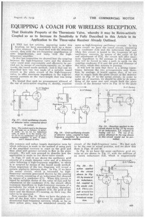
In Figs. 17 and 18 are shown the oscillatory grid circuits of a single detector valve and of a detector valve following a high-frequency amplifier, to which it is coupled by means of the tuned anode method. Close inspection of the two diagrams will reveal a certain similarity between them. In Fig. 17 we have the aerial circuit, which is traversed by ' highfrequency currents generated therein by the passing ether waves, consisting of an inductance (L1) shunted by means of a condenser (C1). When this circuit is tuned by suitable choice of the value of (L1) and by adjustment of the condenser (C1), the circuit offers maximum impedence to high-frequency currents of a periodicity for which it is set, and these, therefore, pass to earth via the condenser (Cm, the grid of the valve and the filament (F) causing, on their way, the valve to be operated.
Now consider Fig. 18. Here we have the plate circuit of the first valve traversed by amplified unidirectional high-frequency currents, which, so far as their action goes, may be considered exactly the same as high-frequency oscillatory currents. In this plate circuit we have the tuned circuit, censisting of. a condenser (C3) and the inductance (L2), and, when this circuit is tuned to the frequency of -our oscillatory currents, by means of the value of 12 and adjustment of (03), the circuit will offer maximum irnpedence to the passage to the, former and they will be forced to take a path to, earth via the coupling condenser (C4) and the grid and filament of the valve, which they actuate in passing.
It will now be seen that there is a strong resemblance between the two arrangements and, there. fore, by analogy, it would appear that, if we are able to couple back theplate circuit of the detector valve in Fig. 17 to the aerial circuit, in order to make use of reaction, we should be able to do something of the same sort and couple back the plate circuit of the detector valve in Fig. 18 to the plate
circuit of the high-frequency valve. We find such to be the case in actual practice, and we show this done in Figs. 16 and 20.
In Fig. 19 we have the same oscillatory grid circuits as are shown in Fig. 17, with the addition of an extra inductance (L3), which is magnetically
coupled to the aerial tuning inductance (L1). As the high-frequency plate currents traverse this inductance, they cause increased high-frequency currents to flow in the grid circuit of the valve which, in their turn, again increase the value of the plate oscillatory currents, and so on, until, if the coupling between Li and L3 is sufficiently tight, the valve will get out of control and oscillate on its own. Before this point is reached, however, an enormous increase in signal strength takes place, hence the value of reaction. Now look at Fig. 20. Here we have the same grid cscillatory circuits as are shown in Fig. 18, with the addition of an extra inductance (L4), which is magnetically coupled to the inductance (L2) in the plate : circuit of the high-frequency amplifying valve. The traversing of this inductance (IA) by the highfrequency plate currents in the plate circuit of the second valve boosts up the grid currents (which are really the plate currents of the first valve), and the amplifying properties of reaction are obtained.
There is, however, this important difference : when reaction in Fig. 19 is pushed beyond the selfoscillation point point of the valve, the large quantity of energy, liberated in the plate circuit of the valve, is transferred from L3 to Li and thence direct to the aerial, which is-strongly energized. In other words, the set becomes a transmitter and interferes with every set for a radius of several miles, to the detriment of the reception of telephony. On the other hand, should reaction be pushed too far in the circuit shown in Fig. 20, the liberated energy has to get across from the plate to the grid of the first valve before it can reach the aerial, and, since the plategrid resistance of the average receiving 'valve is about 70,000 'ohms, this puts a pretty effective stopper on muchenergy reaching the aerial, and thus, the chances of interference are very greatly reduced. This latter circuit is, therefore, permitted by the P.M.G. for the reception of broadcasting, whilst the use of reaction, as shown in Fig. 19, is not.