 1
1 2
2 3
3 4
4 5
5 6
6 7
7 8
8 9
9 10
10 11
11 12
12 13
13 14
14 15
15 16
16 17
17 18
18 19
19 20
20 21
21 22
22 23
23 24
24 25
25 26
26 27
27 28
28 29
29 30
30 31
31 32
32 33
33 34
34 35
35 36
36 37
37 38
38 39
39 40
40 41
41 42
42 43
43 44
44 45
45 46
46 47
47 48
48 49
49 50
50 51
51 52
52 53
53 54
54 55
55 56
56 57
57 58
58 59
59 60
60 61
61 62
62 63
63 64
64 65
65 66
66 67
67 68
68 69
69 70
70 71
71 72
72 73
73 74
74 75
75 76
76 77
77 78
78 79
79 80
80 81
81 82
82 83
83 84
84 85
85 86
86 87
87 88
88 89
89 90
90 91
91 92
92 93
93 94
94 95
95 96
96 97
97 98
98 99
99 100
100 101
101 102
102 103
103 104
104 105
105 106
106 107
107 108
108 109
109 110
110 111
111 112
112 113
113 114
114 115
115 116
116 117
117 118
118 119
119 120
120 121
121 122
122 123
123 124
124 125
125 126
126 127
127 128
128 129
129 130
130 131
131 132
132 133
133 134
134 135
135 136
136 137
137 138
138 139
139 140
140 141
141 142
142 143
143 144
144 145
145 146
146 147
147 148
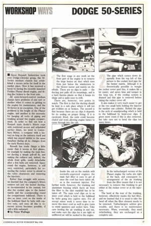
148 The first stage in any work on the front part
Page 129
Page 130
Page 131
Page 132
If you've noticed an error in this article please click here to report it so we can fix it.
of the engine is to remove the large heater air duct which runs from just below the windscreen to the blower motor and matrix on the offside. There are no clips to undo — the ducting just pulls off its mountings, and is a hard therm° plastic so that it keeps its shape and is quite easy to refit.
There are, however, two points to watch. The first is that the ducting should be kept in a safe place where it will not get trodden on or broken. The second is that because there are no clips it depends for its sealing on proper fitting. If it is carelessly fitted, the ends could become chafed and worn allowing engine fumes to come through into the cab. The pipe which comes down diagonally from the top left of this picture is the coolant feed pipe for the heater matrix. Although it is theoretically possible to wangle the rocker cover past this, it makes life a lot easier, and saves time and temper in the long run, if the cooling system is drained and this pipe is removed before taking the rocker cover off.
It also makes it very much easier to get at the two small bolts holding the injector for number one cylinder. Behind the pipe is the arch of soundproofing which is held to the bulkhead by bend-over clips. It gives more room if this is also removed, but take care not to bend the clips too many times.
Inside the cab on the models with normally-aspirated engines the main fuel filter is easy to get at once the cowl has been taken off, as is the rearmost injector. For further work, however, the trunking and aluminium housing which ducts air from the filter to the inlet manifold has to be taken off. The main cowl clips on to an inner cowl which is held to the bulkhead by bolts going into captive nuts. For all except minor work it saves time to remove this inner cowl as well to give room to wield spanners and socket bars. Take care feeding the air trunking in and out, and make sure the clips for it are tight or unfiltered air will be sucked in the engine. In the turbocharged version of the Phaser engine the turbo sits right at the back, and consequent rearrangement of the air thinking from the filter means that it is not necessary to remove this trunking to get either at the rocker cover or at the injectors.
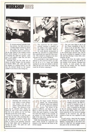
The bend at the rear of the trunking, however, effectively masks the fuel filter, and we learned that it is usual to take the bend off when the filter element needs to be renewed. Turbochargers seldom give trouble, and there is no maintenance necessary. When, eventually, they need refurbishing, they are exchanged as a complete unit. In vacuum-assisted hydraulic braking systems, the fluid reservoir is a wedge-shaped translucent plastic tank under the bonnet. There is an important point to watch here.
All the pipe unions in the braking system have metric threads. It is not just a case of choosing the right-size spanner, make sure if you replace a pipe that you have the correct unions.
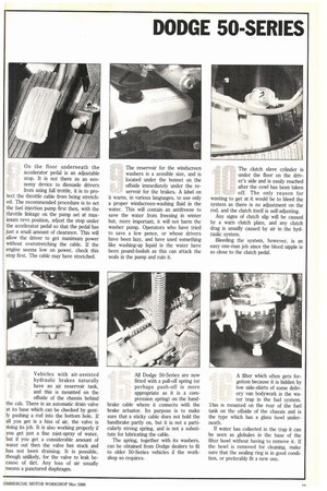
Physically they are the same size as unions on earlier Dodges, but the number of threads differs and, quite apart from the dangers of a leaking system, you will ruin the internal thread on the master cylinder if you force in the wrong one. The reservoir for the powerassisted steering is mounted on the offside of the engine compartment right at the front. There is the usual dipstick incorporated in the filler cap, and there is a paper-element filter underneath the main lid of the reservoir. This should be changed at the intervals given in the service handbook.
It is a good plan to wipe round the area adjacent to the reservoir before you take the lid off as it is a large and inviting opening for any dirt and rubbish to fall into while the lid is off. Check the sealing ring round the lid before replacing it. One very easy thing to get at on the Phaser installation in the 50Series is the air inlet filter. This is mounted high in the engine compartment on the offside. The filter is the normal paper element type, and its life can be extended by tapping it to free dirt and then blowing it clean with a lowpressure air line.
Always blow from the inside towards the outside as most of the dirt will be on the outside of the element. Blowing from the outside, as some people do, only forces the dirt further into the element and shortens its useful life. On the floor underneath the accelerator pedal is an adjustable stop. It is not there as an economy device to dissuade drivers from using full trottle, it is to pro tect the throttle cable from being stretched. The recommended procedure is to set the fuel injection pump first then, with the throttle linkage on the pump set at maximum revs position, adjust the stop under the accelerator pedal so that the pedal has just a small amount of clearance. This will allow the driver to get maximum power without overstretching the cable. If the engine seems low on power, check this stop first. The cable may have stretched. The reservoir for the windscreen washers is a sensible size, and is located under the bonnet on the offside immediately under the reservoir for the brakes. A label on it warns, in various languages, to use only a proper windscreen-washing fluid in the water. This will contain an antifreeze to save the water from freezing in winter but, more important, it will not harm the washer pump. Operators who have tried to save a few pence, or whose drivers have been lazy, and have used something like washing-up liquid in the water have been pound-foolish as this can attack the seals in the pump and ruin it. The clutch slave cylinder is under the floor on the driver's side and is easily reached after the cowl has been taken off. The only reason for wanting to get at it would be to bleed the system as there is no adjustment on the rod, and the clutch itself is self-adjusting.
Any signs of clutch slip will be caused by a warn clutch plate, and any clutch drag is usually caused by air in the hydraulic system.
Bleeding the system, however, is an easy one-man job since the bleed nipple is so dose to the clutch pedal.
Checking and renewing the front brakes is much quicker and simpler now the 50Series is fitted with disc front brakes. The thickness of the pads can be checked after taking the wheel off, and if they need replacing all that has to be undone are the two long split pins at the front of the caliper.
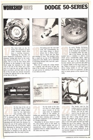
It may be necessary to ease the pads back from the disc with something like a wide, flat-bladed screwdriver before they can be pulled out, but if so check that there is room in the hydraulic reservoir for the fluid which will be displaced by moving the pads. The pads are selfadjusting for wear. On larger model 50-Series chassis, the vacuum-assisted hydraulic brakes are replaced by an air-pressure-assisted system. The layout of the system is different, and there are extra filters to check and clean. One of these, which often gets forgotten, is about halfway down the chassis on the nearside. In our picture it is the housing just to the right of the main valve, and has four bolts holding on a bottom plate.
Under this bottom plate is the filter element which should be inspected and cleaned at the intervals [aid down in the service manual. On the air-assisted hydraulic braking system, the fluid reservoir is mounted on top of the master cylinder which, in turn, is mounted on the back of the air actuating chamber just behind the cab on the offside. There is an electrical connection for the low-level warning attached to the reservoir cap, and the contacts of this are very exposed to road dirt At each service, check that the warning is working by lifting up the cap. As well as lighting a warning light on the dash in the event of a fluid loss, the warning system also puts on the cab interior light. Vehicles with air-assisted hydraulic brakes naturally have an air reservoir tank, and this is mounted on the offside of the chassis behind the cab. There is an automatic drain valve at its base which can be checked by gently pushing a rod into the bottom hole. If all you get is a hiss of air, the valve is doing its job. It is also working properly if you get just a fine mist-spray of water, but if you get a considerable amount of water out then the valve has stuck and has not been draining. It is possible, though unlikely, for the valve to leak because of dirt. Any loss of air usually means a punctured diaphragm. All Dodge 50-Series are now fitted with a pull-off spring (or perhaps push-off is more appropriate as it is a compression spring) on the hand brake cable where it connects with the brake actuator. Its purpose is to make sure that a sticky cable does not hold the handbrake partly on, but it is not a particularly strong spring, and is not a substitute for lubricating the cable.
The spring, together with its washers, can be obtained from Dodge dealers to fit to older 50-Series vehicles if the workshop so requires. A filter which often gets forgotton because it is hidden by low side-skirts of some delivery van bodywork is the water trap in the fuel system.
'this is mounted on the rear of the fuel tank on the offside of the chassis and is the type which has a glass bowl underneath.
If water has collected in the trap it can be seen as globules in the base of the filter bowl without having to remove it. If the bowl is removed for cleaning, make sure that the sealing ring is in good condition, or preferably fit a new one. The front hubs on the 50Series are mounted on taper roller bearings which must have a running clearance. Tightening the nut fully can cause dangerous overheating. There is a clearance setting laid down in the workshop manual involving the use of a dial guage, but it is not an easy check when the grease in the bearings is cold. Some fitters judge the clearance by the slight rock at the rim of the wheel, but a safer way is to spin the nut up tight while the hub is revolved, and then back it off one flat of the nut plus any amount necessary to bring the split-pin hole in line with one of the slots in the nut. Oil leaking past the rear hub seals and contaminating the rear brake linings is almost always due to fitters forgetting to check that the back axle breather is clear, The breather looks like a small nut on top of the differential casing just to the offside, and is vulnerable to becoming blocked with road dirt, particularly in winter.
When the air inside the casing warms up it expands, and will force oil past the seals if the breather is blocked. Check it on each service by undoing it and blowing it out with an air line. In early Dodge 50-Series chassis the spare wheel had to be humped up manually to its mounting under the nearside of the chassis, but later =deli have a windlass to wind it up which saves considerable effort. Since spare wheels are not used all that often, however, the gear in the windlass can become seized, and to prevent this there is a grease nipple on the top of the housing. Failure to grease it could result in a driver being unable to use the spare wheel in the event of a puncture. It also pays to smear grease on the exposed wire cable.
On the step of the cab on the driver's side is a plate giving the setting dimension for the light-laden load sensing brake valve on the rear axle. The setting dimension "Y" is checked with the vehicle unladen. To check it, undo the pin holding the top end of the spring at the end of the value operating arm and check the distance between the eye of the spring and the hole in the end of the arm. If necessary, adjust the dimension by altering the position of the nut at the base of the spring. The dimension is stamped on the plate by the supplying dealer after the body is fitted.
On the inside of the driver's door is a sheet which gives details of all the main items of equipment fitted to the chassis, including any special-order equipment. This is useful when ordering parts as it will identify the equipment to any storekeeper in a Dodge dealership.
Remember in all cases always to quote the code number given on the sheet, as well as the chassis number and year of manufacture when ordering parts, as equipment fitted to similar models built in the same year may vary. The header tank for the cooling system is mounted on the bulkhead under the bonnet, and can be awkward to top up unless you have either a forecourt water pipe or a water can with a long curved spout. Should the radiator itself need to be removed, undo the bolts holding the top plate to the front grille and then two bolts holding the top of the radiator. Then the radiator just lifts out of two rubber-bushed holes at its base. When refilling, follow the notes in the service handbook, or air can become trapped in the heater system making it ineffective.