


Improved Scavenging for Twostroke Oilers
Page 48
If you've noticed an error in this article please click here to report it so we can fix it.
A Resume of Recently Published Patent Specifications Obtainable from the Patent Office, Price s. each
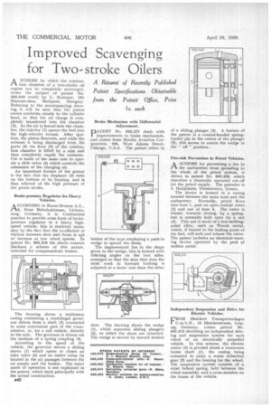
ASCHEME by which the combustion chamber of a two-stroke oil engine can be completely scavenged, forms the subject of patent No. 502,549 (void) by G. Kammer, 15b Muzeum-utca, Budapest, Hungary Referring to the accompanying drawing, it will be seen that the piston crown conforms closely to the cylinder head, so that the air charge is completely transferred into the chamber (2). As the air is forced into the chamber, the injector (1) sprays the fuel into the high-velocity stream. After ignition, the piston descends, and while the exhaust is being discharged from the ports (5) the floor (3) of the combustion chamber is lifted by a cam and thus completely expels the contents. Use is made of the same cam to operate a slide valve (4) which controls the admission of the charging air.
An important feature of the patent is the fact that the displacer (3) rests on the bottom of its housing, and is thus relieved of the high pressure of the power stroke, Brake-pressure Regulator for Heavy Vehicles.
A CGORDING to Knorr-Brernse A.G.,
Neue Bahnhoistrasse, Lichtenberg, Germany, it is Continental practice to provide some form of brakepressure regulator in a heavy highspeed vehicle; this is rendered neces'sary by the fact that the co-efficient of friction between shoe and drum is apt to increase at low wheel speeds. In patent No. 502,318 the above concern discloses a scheme of this nature, intended for compressed-air brakes.
The drawing shows a stationary casing containing a centrifugal governor driven from a shaft (2) connected to some convenient part of the transmission, or, for a rail vehicle, directly to the axle. The governor is driven via the medium of a spring coupling (3).
According to the speed of the vehicle, the governor moves a sliding sleeve (1) which opens or closes an inlet valve (5) and an outlet valve (4) located in the air passages between the air supply and the brakes. The exact mode of operation is not explained in the patent, which deals principally with the actual construction.
B42
Brake Mechanism with Differential Adj us tment PATENT No. 502,277 deals with improvements to brake mechanism, and comes from Bendiit Aviation Corporation, 105, West Adams Street, Chicago, U.S.A. The patent refers to
brakes of the type employing a push-in wedge to spread the shoes.
The improvement lies in the shape given to the wedge; this is formed with differing angles on the two sides, arranged so that the shoe that does the most work in forward braking is adjusted at a faster rate than the other shoe. The drawing shows the wedge (1), which separates sliding plungers (2), to which the shoes are attached. The wedge is moved by inward motion of a sliding plunger (3). A feature of the patent is a conical-headed springloaded pin in the centre of the plunger (5); this serves to centre the wedge in the " oil" position.
Fire-risk Prevention in Petrol Vehicles.
ASCHEME for preventing a fire in the carburetter from spreading to the whole of the petrol system, is shown in patent No. 502,328, which describes a thermally operated cut-off for the petrol supply. The patentee is S. Hadjidakis, Thessalonica, Greece.
The device is housed in a casing located between the main tank and the carburetter. Normally, petrol flows • into bore 1, past an open conical valve (2) and out of bore 4. The valve is biased, towards closing, by a spring, but is normally held open by a nut (3). This nut is made of a low-meltingpoint alloy, such as Woods metal, which, if heated to the boiling point of the fuel, will melt and release the valve. The patent includes an electrical-warning device operated by the pool of molten metal.
Independent Suspension and Drive for Electric Vehicles.
FROM Bleichert Transportanlagen G.m.b.H., 15 Bleicherstrasse, Leipzig, Germany, comes patent No. 502,313 decribing an independent driving and suspension system for each wheel of an electrically propelled vehicle. In this scheme, the electric motor (3) is pivoted about a transverse frame shaft (1), the casing being extended to carry a worm reduction gear (2) and the bearing for the wheel. The suspension system consists of a stout helical spring, held between the wheel assembly, and a cross-member on the frame of the vehicle.