


A Fuel Injection Pump
Page 68
If you've noticed an error in this article please click here to report it so we can fix it.
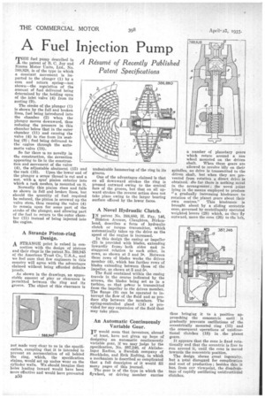
MITE fuel pump described in 1 the patent of B. C. Joy and Sinune Motor Units, Ltd., No. 388,828, is of the type in which a constant movement is imparted to the plunger (1) by a mun and return spring—not shown—the regulation of the amount of fuel delivered being determined by the holding open of the inlet valve (4) from its seating (9).
The stroke of the plunger (1) is shown by the full and broken lines, fuel being introduced into the chamber (2) when the plunger moves downward, thus reducing the pressure in this chamber below that in the outer chamber (11) and causing the valve (4) to rise from its seating (9) ; fuel being delivered to the' engine through the automatic valve (18).
So far there is no novelty in the construction, the invention appearing to lie in the construetion and movement of the valve (4), the adjustable abutment (15) and the rack (16). Upon the lower end of the plunger a screw thread is cut and a nut, with a spur pinion exterior into which a rack meshes, is mounted on it.
Normally this pinion rises and falls as shown in full and broken lines, but should the quantity of fuel required be reduced, the pinion is screwed up the valve stem, thus causing the valve (4) to remain open for some part of the stroke of the plunger, and allowing part of the fuel to return to the outer chamber (11) instead a being injected into the engine.
A Strange Piston-ring
Design.
A STRANGE point is raised in con
nection with the design of pistons and their rings in the patent No. 388,945 of the American Trust Co., U.S.A., and we feel sure that few engineers in this country will agree with the advantages claimed without being afforded definite proofs.
As shown in the drawings, an appreciable amount of play or clearance is permitted between the ring and its groove. The object of this clearance is not made very clear to us in the specification, excepting that it is intended to prevent an accumulation of oil behind the ring, which, the specification claims, would set up undue wear on the cylinder walls. We should imagine that holes leading inward would have been more effective and would have prevented B50 undesirable hammering of the ring in its groove.
One of the advantages claimed is that on all downward strokes the ring is pressed outward owing to the conical face of the groove, but that on all upward strokes the reverse action does not take place owing to the larger bearing surface offered by the lower faces.
A Novel Hydraulic Clutch.
IN patent No. 388,880, H. Fay, 146, Bidston Avenue, Claughton, Birkenhead, describes a form of hydraulic clutch or torque transmitter, which automatically takes up the drive as the speed of the engine is increased.
In this design the casing or impeller (2) is provided with blades, extending inwardly from) both sides and in staggered relation to each other, in rows, as shown at 3 and 3. Between these rows of blades works the driven member (4), which has further rows of blades extending between those of the impeller, as shown at 5 and 5a.
The fluid contained within the easing travels in the course indicated by the arrows, the blades being set as in a turbine, so that poAver is transmitted from the impeller to the driven member. The flange (9) can be operated to interrupt the flow of the fluid and so produce slip between the members. The spring-controlled gland (14) is provided for any expansion of the fluid that may take place.
An Automatic Continuously Variable Gear.
IT would seem that inventors, abroad at least, have not given up hope of designing an automatic continuously variable gear, if we may judge by the specification, No. 387,246, of Aktiebolaget Radius, a Swedish company of Stockholm, and Erik Rafting, in which a mechanism is described so complicated that a full deseripton of it would fill many pages of this journal.
The gear is of the type in which the flywheel, or driving member carries
a number of planetary gears which rotate around a sun wheel mounted on the driven shaft. When these gears are
allowed to revolve idly on their spindles, no drive is transmitted to the driven shaft, but when they are prevented from rotation a direct drive is obtained. iSo far there is nothing novel in the arrangement; the novel point lying in the means employed to produce "a gradually increasing hindrance to rotation of the planet gears about their own centres." This hindrance is brought about by a sliding eccentric cone, governed by centrifugally operated weighted levers (28) which, as they fly outward, move the cone (26) to the left,
thus bringing it to a position approaching the concentric until it gradually prevents oscillations of the eccentrically mounted ring (15) and the consequent operations of unidirectional clutches (18) in . the planet gears.
It appears that the cone is fixed rotationally and that the eccentric is free to run around it, until the cone is moved towards the concentric position.
The, shows great ingenuity, but atotal disregard for complication and cost of production ; besides this it has, from our viewpoint, the disadvantage of rapidly oscillating unidirectional clutches.