


TWO NEW METHODS OF FORMING TEETH.
Page 32
If you've noticed an error in this article please click here to report it so we can fix it.
A Resume of Recently Published Patent Specifications.
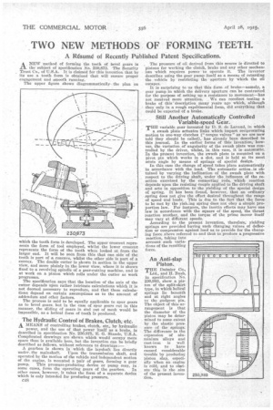
ANEW method of forming the teeth of bevel gears is the subject of specification No. 230,873. The Security Trust Co., of U.S.A. It is claimed for this invention that by ,
Its use a tooth form is obtained that will ensure proper engagement and smooth running.
The upper figure shows diagrammatically the plan on
which the tooth form is developed. The upper crescent represents the form of tool employed, whilst the lower crescent represents the form of the tooth when looked at from the larger end. It will be seen from this that one side of the tooth is part of a concave, whilst the other side is part of a convex. The double cutter is shown in section in the upper view, and more plainly in the lower view, where it is shown fixed to a revolving spindle of a gear-cutting machine, and is at work on a pinion which rolls under the cutter as work progresses.
The specification says that the location of the axis of the cutter depends upon rather intricate calculations which it is not deemed necessary to reproduce, and that these calculations depend on certain assumptions as to the amount of addendum and other factors.
The process is said to be equally applicable to spur gears as to bevel gears, but in the case of spur gears cut in this manner, the sliding of gears in and out of mesh would be impossible, as a helical form of tooth is produced.
The Hydraulic Control of Brakes, Clutch; etc.
MEANS of controlling brakes, clutch, etc., by hydraulic power, and the use of that power itself as a brake, is described in specification No. 230,875, E. G. Stands, U.S.A. Complicated drawings are shown which would occupy more space than is available here, but the invention can be briefly described as follows, without reference to drawings :— A gearbox is shown in which the layshaft lies directly under, the mainshaft. Upon the transmission shaft, and operated by the motion of the vehicle and independent motion of the engine, is mounted a pair of gears, forming a gear
pump. This/ pressure-prodficing device or pump may, in some cases, form the operating gears of the gearbox. In other cases, however, it takes the form of a separate device which is only intended for producing pressure.
C48 _ The pressure of oil derived from this source is directed to pistons for working the clutch, brake and any other mechanism which requires power to operate it. The inventor describes using the gear pump itself as a means of retarding the vehicle by restricting the• aperture by which the oil escapes.
It is surprising to us that this form of brake—namely, a gear pump in which the delivery aperture can be contracted for the purpose of setting up a resistance to movement—has not received more attention. . We can recollect testing a brake of this description many years ago which, although then only in a rough expelimental form, did everything that could be expected of a brake.
Still Another Automatically Controlled Variable-speed Gear.
TEE variable gear invented by D. S. de Lavaud, in which a swash plate actuates links which impart reciprocating
motion to one-way clutches (" torque valves" as we are now told they should be called), has already been described in this journal. In the earlier forms of this invention, howver, the variation or angularity of the swash plate was controlled by the driver, whilst, in this case, it is automatic. In the present invention, the swash plate is mounted on a pivot pin which works in a slot, and is held at its most acute angle by means of springs of special design.
In this ease the change of speed takes place automatically
in accordance with the load. The automatic action is obtained by varying the inclination of the swash plate with respect to the driving shaft, under the influence of the reaction exercised by the connecting rods, which reaction depends upon the resisting couple applied to the driving shaft and acts in opposition to the yielding of the special design of spring. It has been found, however, that an ordinary spring does not give the effect desired throughout the range of speed and loads. This is due to the fact that the force to be met by the yielsingspring does not obey a simple proportion law. For instance, the inertia effects may have one law in accordance with the square of the speed, the thrust reaction another, and the torque of the prime mover itself may vary at different speeds. According to the present invention, therefore, yielding springs are provided having such changing values of deflection or compression against load as to provide for the changing force above referred to and thus to produce a progressive reaction, taking into account such variations of the resulting force.
An Anti-slap Piston.
THE Daimler Co., Ltd., and H. Bush, in specification No. 230,083, show a piston of the split-skirt type, in which helical springs lie beneath and at right angles to the gudgeon pin. The object of this arrangement is that the diameter of the piston may he deter mined to some extent by the elastic pressure of the springs. The differeuee in the expansion of aluminium alloys and cast-iron is well known to have caused considerable trouble by producing piston slap, especially when an engine is cold, and to 0bl/slate this is the aim of the present invention.