


THE USE AND IMPROVEMENT OF LATHES.
Page 31
If you've noticed an error in this article please click here to report it so we can fix it.
Practical Points Put Forward by Our Driver and Mechanic Readers.
AMISCELLANY of ideas is given this week in connection with methods of using lathes of various patterns, and home-made devices for increasing the utility of such machine tools.
When much sawing or filing has to be done, a rig for attachment to a lathe, in order to utilize its mechanical effort, is an advantage. " B.H.Is." of Wash ington, D.C., forwards a descriptiou of an arrangement -which appears to be
serviceable in this connection. This week's prize of 15s. is awarded to him. As will be seen from the. illustration, a support is made having two right angles in its length. One horizontal portion is considerably longer than the other, the greater of the two being bolted to the lathe bed ; the shorter one, parallel to the bed, has riveted to it a suitable faceplate. Attached to the vertical portion of the support are two guides in which the vertical driving bar for the saw holder moves. The U-shaped saw or file holder is fastened to the driving bar, and a suitable aperture is made in the faceplate, through which the saw holder is threaded, the hole being made of such a size that the holder is a working fit in it.
In this way, the vertical' driving shaft is guided at two points, and the saw holder at one point. The vertical motion is imparted to the bar by a cranked shaft fitted into the headstock of the lathe engaging with a suitable lug on the driving bar shaft of the saw holder. The hole in this lug, of course, is in the form of a horizontal slot to allow the cranked shaft to travel laterally as well as rotate.
TRUEING up a crankshaft between lathe centres with an emery stick is not always satisfactory, according to " of Rotherham, and he suggests an improvement for finishing purposes. The main portion of the tool employed is an ordinary hacksaw blade. In place of the usual blade a leather belt with steel fasteners at each end is fixed into position and a piece of emery cloth glued on to the leather. "11.11." claims that the use of this device causes no fiats to be made on the shaft, as is the case when an emery stick is used.
CUTTING a Woodruff keyway in a shaft is not always easily accomplished -without proper milling appli
-mice& "H.R.I.," of Bridlington, describes a method which he has employed at various times. Two pieces of hard wood were taken and hinged together, the lower one being bolted down to the saddle on the lathe bed with four bolts. Two pieces of steel 1 in. by in. were drilled to clamp the shaft on to the upper piece of hard wood at right angles to the lathe centres and the four neces
sary bolts inserted. A wedge-shaped wooden block was taken and placed between the two hinged wooden parts in order to raise or lower the shaft bolted to the upper one, thus approaching or departing from the rotating cutter in accordance with the extent to which the wedge is pulled or pushed backwards and forwards.
A milling cutter was run between centres on a mandrel; by pressing on the end of the shaft by hand and pushing up the wooden wedge the shaft was brought into contact with the rotating cutter.
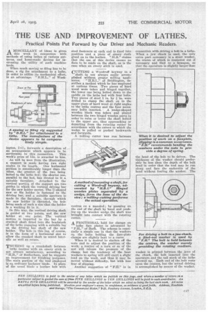
A FRICTIONAL hold for clamps on lathe face plates is advocated by " of Bath. The scheme is essentially a simple one in that the washers on the bolts holding the face-plate clamps are slightly bent to a curve.
When it is desired to slacken off the nuts and to adjust the position of the work, a matter of a turn or so of the nut will release the pressure of the clamp, but the tendency of the bent washers to spring -will still exert a slight load on the work, and thus it may be moved without difficulty, but with less fear of slipping.
Another suggestion of "P.11." is in connection with driving a bolt in a lathe. When a jaw chuck is used, the only extra part necessary is a stout washer, the centre of which is reamered out if necessary and filed to a hexagon, so that the aperature is slightly larger than the head of the bolt to be driven. The thickness of the washer should preferably be less than the depth of the bolt head in order that the tool may be run along and face the underside of the heads without fouling the washer. The washer is gripped between the jaws of the chuck, the bolt inserted into the aperature and the tail stock of the lathe screwed up. Each end of the bolt rests npon the centres, but the actual driving is accomplished by means of the washer.