


SIMPLE
Page 70
If you've noticed an error in this article please click here to report it so we can fix it.
Circuits and cables,
THE wiring diagram for a modern motor vehicle which shows all the electrical components and with dozens of lines indicating all the circuits is likely to prove very confusing, but if each circuit is extracted from the main diagram and considered singly it becomes much simpler.
The electrical system may be regarded as a portable power station where a diesel or petrol engine drives either a dynamo, or more likely, an alternator, to provide the electrical power for all the electrical components. (My photo shows an example of this "power plant" — in this case, a dynamo).
Because the alternator or dynamo will not be generating when the vehicle is stationary with the engine stopped, and it is still necessary to draw electrical power from the system, there must be an electrical energy storage system to fall back on. The battery serves this purpose.
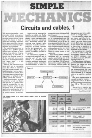
Internal-combustion engines have to be turned over before they will start so a starter motor must be provided for this purpose. If a petrol engine is used provisions must be made for a spark at the sparking plug to fire the mixture in the cylinders, so an ignition system is required. Lights must be provided for travelling at night and finally, various electrical accessories are needed. Under this heading are included direction indicators, horn, windscreen wipers and washers, cigar lighters, radio, and so on. These five circuits — charging, starting, ignition, lighting and accessories — are illustrated in Figure 1, grouped around the battery, the heart of the system.
• The cables linking together all the electrical equipment are an essential part of any motor vehicle. It is important when installing additional equipment, or replacing cables which have become damaged, to make sure that a cable of the right specification is used.
A cable's resistance depends on its cross-sectional area (its thickness) and its length. Obviously cables should be kept as short as possible, but there is a limit to how short they can be — they must be no shorter than the distance between the two components they connect. So the choice is really limited to the cable size.
If too small a cable is used the resistance will be excessive, causing overheating and a reduced voltage at the appliance end of the cable. This difference between the supply voltage and the voltage actually present at the appliance end of the cable known as voltage drop.
To give flexibility, cables use on motor vehicles have i number of thin strands of win rather than one single thicke strand. Cable sizes are denote( by two figures, the first relatind to the number of strands in thl cable, and the second to th, thickness of each strand.
For example, a wire classified as 9/0.30 is one having nin, strands each 0.30mm in diame ter; 37/0.71 indicates a cabl, with 37 strands each 0.71mm ii diameter and so on.
The Table below details som, popular cable sizes with their re sistance per metre and wher they can be used.
The Table only shows some the cables available, the manu facturers will be pleased to ad vise customers as to the exac cable to be used for a particula duty.
Very much heavier cables ar needed for starter motors — range from 37/0.71 to 61/1.1 with a continuous current ratin, from 105 to 415 amps is avai able.
More about cables an connections in the next article
by Preceptc