


Fabricating Axle Casings from Sheet Metal
Page 48
If you've noticed an error in this article please click here to report it so we can fix it.
A Résumé of Recently Published Patent Specifications
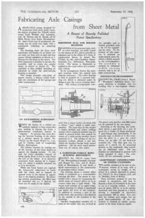
A REAR-AXLE casing, designed for rt production from sheet metal, forms the subject of patent No. 578,449, which comes from Weida11 and Assembly, Ltd., M. Burton and H. Marsh, all of Mitre Works, Eyre Street, Birmingham, 18. Apart from ease of production, the casing can be made very light, with a consequent reduction in unsprung weight.
The drawings show the three main operations; the blanks (I), of which two are used, are bent over at each end into square tubular members, as shown at 2, leaving two flat faces in the centre. The third operation is forcibly to shorten the assembly, and so create the central banjo, as shown in sketch (3). The assembly is then welded, including an end-plate to which the shaft-bearing housing is attached.
This design provides axle-tubes of square section, a feature which facilitates the attachment of the springs and other components.
AN ANTI-DIPPING SUSPENSION SYSTEM WHEN the brakes of a vehicle are VV suddenly applied, a force comes into play tending to depress the front, a phenomenon commonly known as "dipping." To prevent this, even during the heaviest braking, is the object of a scheme shown in patent No. 578,225, by the Austin Motor Co., Ltd., and H. Charles, both of Longb ridge Works, Birmingham.
The scheme operates by making use of the reaction of the front brakes to oppose the dipping motion. To this end, the brake assembly, instead of being rigidly fixed, is free to rock about the axis of the wheel. It is, however, restrained from motion by a torquearm (I), which is slidably attached (as at 2) to the frame.
When the front brakes are applied, the torque-arm endeavours to rotate with the wheel, and so imparts an upward force to the chassis in opposition to the dipping tendency. By choosing suitable proportions, the effect may be cancelled out, or, if desired, the front can be made to rise slightly. DIRTPROOF SEAL FOR ROLLER BEARINGS
DEAR INGS of the precision type, such Li as roller bearings, are easily ruined by the ingress of dirt, and to provide an adequate seal is the object of a form of construction shown in patent No. 577,624, by the Allis-Chalmers Manufacturing Co., Milwaukee, Wisconsin, U.S.A. The device is illustrated as applied to the track'rollers of a crawlertype vehicle.
In the arrangement shown, the outer part revolves while the central axle remains stationary. The roller bearing is held in position by .a screwed lockring (I), which is shimmed under its flange to give the correct working clearance. The sealing arrangements corn
prise first a metal washer (2) fitted with a rubber tyre," which is under compression. The outer face of this washer is highly finished and makes rubbing contact with a similarly finished ring (3), which is pressed firmly into contact by means of a multi-spring member shown generally at 4. The mating of the two precision surfaces affords a seal into which the smallest foreign body cannot penetrate. All the more usual precautions are, of course, also taken.
A PASSENGER-VEHICLE BODYBUILDING REFINEMENT
PATENT No. 578,215 comes from the Metropolitan-Cammell Carriage and Wagon Co., Ltd., and F. Rayer, both of Birmingham, 8, and shows a detail improvement in the construction of passenger-vehicle bodies.
The drawing shows a vertical pillar which is connected to a cross-member carrying the floor. The patent is concerned with a means for connecting the whole series of vertical pillars so as to convert them into a rigid whole. The means used consists of an upper longitudinal pressing 11), which is positioned just below the level of the windows. In addition to forming a part of the girder-work, this pressing is also finished on the outside to the standard of the panelling.
Another longitudinal member (2) is used on the inside; this, too, is fixed to the uprights and is further provided with a lip (3) for supporting the seats. To the bottom of this member is attached an angle-section piece (4), which is firmly secured to the cross-members. The assembly is claimed to withstand widely varying stresses, and is yet of light construction.
ENGINE-CUM-TRANSMISSION
DATENT No. 578,483, from L. Bacon, " Woodrow," Asheldon Road, Torquay, discloses a complete unit for building into a rear-engined vehicle.
The power unit, gearbox and differential are all enclosed in the one casing.
Referring to the drawing, the crankshaft drives a gear-shaft via a pair of gears (1), a clutch (2) being interposed. A gear-change unit, presumably of the epicyclie type, is shown at 3; this transmits the drive to a gear (4), which drives, via an idler (5), the back-axle assembly (6).. 'The idler gear can, by means of a clutch (7), be connected directly to the crankshaft, thus providing an additional ratio. The two clutches are interlocked to prevent both being engaged at once. The axleshafts (8) are universally jointed.
LIGHTWEIGHT CONSTRUCTION OF ENGINE CYLINDERS
TO enable cylinders to be cast in aluminium instead of in iron, with a consequent saving in weight, is the object of a scheme disclosed in patent No. 578,217, by Aero Engines, Ltd., and G. Halliday, both of Bristol.
These inventors propose to cast the cylinder in aluminium, and then to deposit a layer of chromium in the bore to act as a wearing surface. A thickness of about .010 in. is to be initially deposited, and then ground to a finish, leaving a remainder of chromium approximately .004 in. thick, Not only does the scheme save weight, but the good heat-conductivity of the aluminium is claimed to enable greater power to be taken from an engine.