


A Spark-ignited Oil Engine
Page 54
If you've noticed an error in this article please click here to report it so we can fix it.
A Resume of Patent Specifications that Have Recently Been Published
A HEAVY-OIL engine, in which the carburetted mixture is compressed and heated in a separate chamber before being admitted to the cylinder, is shown in patent No. 432,870 (void) by E. V. Reno, of Chabreloche, France. The accompanying drawing shows a four-stroke engine working on the proposed principle. In this case the piston has two diameters, the upper portion being conventional, whilst the lower end works in a larger extension of the cylinder forming an annular working space (4). A two-way-slide valve (2) controls the gas flow in the lower cylinder.
In operation, the mixture arrives via pipe 3 and is admitted by the slidevalve to space 4 on the down-stroke, whilst the firing stroke occurs in the upper cylinder. On the exhaust stroke, the mixture in the lower cylinder is compressed and stored in a chamber (1 and 6) surrounded by the exhaust conduit (5), and is claimed to be completely vaporized in the process. The usual inlet valve takes its supply from this chamber, which is charged twice in every working cycle of the engine.
An Equalizing Valve for Injection Pumps.
T0 relieve excess 'pressure in the pipe lines of an injection system and so eliminate dribble is the object of patent No. 433,231 by C. W. Lawson, 80, Shrewsbury Lane, London, 5.E.18, and Bryce, Ltd., Kelvin Works, Hack
bridge, ,Surrey. The essence of the scheme consists in the provision in the pump barrel of a free plunger (3), the exact location of which is determined by the relative pressures of upper and
lower springs 6 and 4. During injection -this plunger is lifted by the pressure until the cross-bore (1) is clear of shoulder 5, after which the fuel may pass.
After injection, should any undue pressure remain in the pipe line, the plunger (3) is zno%, in a downward direction against spring 4 for a distance sufficient either to reduce the pressure, or in extreme cases to permit the return of the fuel through a lengthwise slot (2).
B44
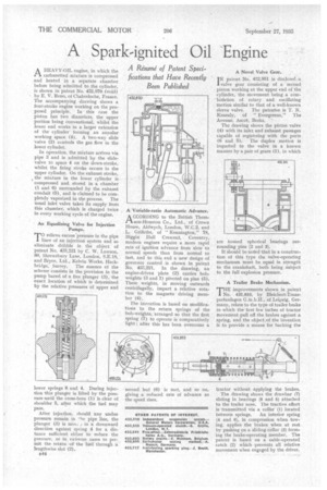
A Variable-ratio Automatic Advance.
A CCOKDING to the British Thomt't son-Houston Co., Ltd., of Crown House, Aldwych, London, W.C.2, and L. Griffiths, of " Kennington," 78, Biggin Hall Crescent, Coventry, modern engines require a more rapid rate of ignition advance from slow to normal speeds than from normal to fast, and to this end a new design of governor control is shown in patent No. 433,221. In the drawing, an engine-driven plate (2) carries bobweights (3 and 1) pivoted on pins (5). These weights, in moving outwards centrifugally, impart a relative rotation to the magneto driving member (4).
The invention is based on modifications to the return springs of the bob-weights, arranged so that the first spring (7) to operate is comparatively light : after this has been overcome a A Novel Valve Gear.
IN patent No. 432,951 is disclosed ;a
valve gear consisting of a second piston working at the upper end of the cylinder, the movement being a combination of rotary and oscillating motion similar to that of a well-known sleeve valve. The patentee is T. N. Kenealy, of "Evergreens," The Avenue, Ascot, Berks. '
The drawing shows the piston valve (4) with its inlet and exhaust passages capable of registering with the ports (6 and 5). The duplex motion is imparted to the valve in a known manner by a pair of gears (1), in which are housed spherical bearings surrounding pins (2 and 3).
It should be noted that in a construction of this type the valve-operating mechanism must be equal in strength to the crankshaft, both being gubject to the full explosion pressure.
A Trailer Brake Mechanism.
THE improvements shown in patent J. No. 432,853, by Bleichert-Transportanlagen G.in,b.H., of Leipzig, Germany, relate to the type of trailer -brake in which the first few inches of tractor movement pull off the brakes against a spring, and the object of the invention is to provide a means for backing the
tractor without applying the brakes.
The drawing shows the drawbar (7) sliding in bearings (8 and 5) attached to the trailer nose. The tractive effort is transmitted via a collar (1) located
between springs. An interior spring (4 and 6), in compression when towing, applies the brakes when at rest by pushing on a sliding collar (3) forming the brake-operating member. The patent is based on a cable-operated catch (2) which prevents all relative movement when engaged by the driver.