Rapid strides forward have been made by Bedford in computer
Page 83

Page 84

Page 85

If you've noticed an error in this article please click here to report it so we can fix it.
aided design. Tim Blakemore met the company's director of engineering and design to catch up with its developments in this area
A REVOLUTION is taking place at Luton and the general public is completely unaware of it, even though similar revolu tionary moves are also occurring in such places as Dunton in Essex, Preston, Eindhoven, Lyons and Stuttgart.
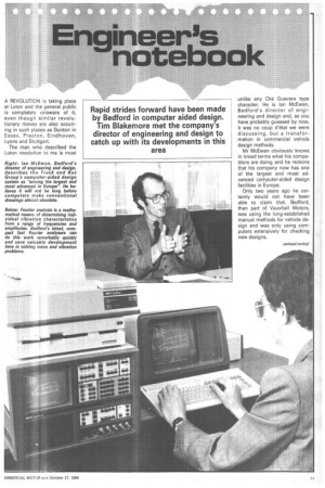
The man who described the Luton revolution to me is most unlike any Che Guevara type character. He is Ian McEwan, Bedford's director of engineering and design and, as you have probably guessed by now, it was no coup d'etat we were discussing, but a transformation in commercial vehicle design methods.
Mr McEwan obviously knows in broad terms what his competitors are doing and he reckons that his company now has one of the largest and most advanced computer-aided design facilities in Europe.
Only two years ago he certainly would not have been able to claim that. Bedford, then part of Vauxhall Motors, was using the long-established manual methods for vehicle design and was only using cornputers extensively for checking new designs. A rapid change has taken place in this areas as a direct result of the formation in 1982 by General Motors of its Truck and Bus Group, and the decision that Bedford was to play a significant role in that group. If the engineers and draftsmen at Luton were going to work on parallel projects and share design data with their counterparts at Pontiac, Michigan, clearly they had to be using the same systems.
Two new computer systems, designated CADAM and CGS, have been installed at Luton, and Bedford's Engineering Analysis facilities have been up-graded. The result is that Bedford now has a total of 110 computer terminals with visual display units in use in engineering and design work. There are still some drawing boards to be seen at Bedford's Engineering Centre, but their future prospects appear no better than those of steam locomotives.
Ian McEwan explained the differences between his two new computer systems, and the timetable of their installation. He began by describing the three main activities in a GM vehicle design cycle as "mechanical and electrical design; body design, and engineering analysis".
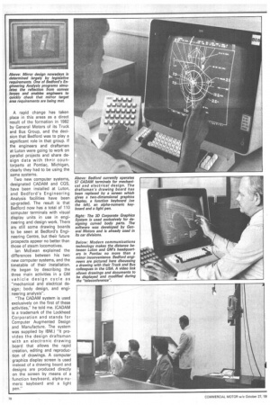
"The CADAM system is used exclusively on the first of these activities," he told me. (CADAM is a trademark of the Lockheed Corporation and stands for Computer Augmented Design and Manufacture. The system was supplied by IBM.) "It provides the design draftsman with an electronic drawing board that allows the rapid creation, editing and reproduction of drawings. A computer graphics display screen is used instead of a drawing board and designs are produced directly on the screen by means of a function keyboard, alpha-numeric keyboard and a light pen."
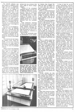
The CADAM software was first installed on Bedford's main frame computer in September 1982 and two terminals were used initially for training, or "hands-on experience" as the computer jargon has it. Any concern there might have been about Bedford's draftsmen adapting to the new equipment proved to be wholly unfounded, I was told. It seems that once almost any draftsman begins to understand the potential of a computerised "drawing board" he is keen to exploit it fully.
Now there are 57 CADAM terminals at Luton. Ian McEwan went on to describe the role they would play in a Truck and Bus Group new vehicle project: "Following approval, the engineering specification for the project is released to the design areas.
"The mechanical and electrical drafting areas, using CADAM, commence design layouts for the major parts of the vehicle to generate information for the build of prototype vehicles.
"When layouts and drawings are sufficiently complete to allow parts to be made or ordered from suppliers, the drawings are issued for experimental purposes. Hard copy plots of the electronic drawings are taken from the electrostatic plotters or the Kongsberg flatbed drafting machine. Magnetic tapes can be supplied to component suppliers who have a compatible system to shorten design time.
"Prototype vehicle build then commences with the assembly of the parts designed on CADAM. Liaison with the design drafting and design engineering groups over any problems that occur helps to ensure design integrity.
"Testing of the completed prototype vehicle is carried out at Bedford's Millbrook proving ground. Tests for durability vibration, performance, safety (for example) show any weaknesses in the design. Any refinements necessary can be speedily carried out on layouts retrieved from the computer files.
"Final production drawings are then completed and issued to downstream departments. These released drawings will be moved to the CADAM data base and stored on disc, for instant retrieval for reference or future projects."
Such is the remarkable pace of development in the compu ter industry that, though CADAM has been at Bedford for no more than two years, already a refinement to it is under consideration.
CATIA is a three-dimensional computer-aided and manufacturing system which was developed by Dassault Systernes of Paris. Design data can be passed between it and the CADAM system.
The CGS (Corporate Graphics System) was developed inhouse by GM because, "in this area we believe our own software is best", explained Mr McEwan. The version being used by the Truck and Bus Group is similar to the one used by GM's car making divisions. CGS has to be a three-dimensional system because it is used for body design. Mr McEwan detailed how Bedford's 22 CGS graphics terminals are used: "When a vehicle project has been approved, the design department prepares a full-size clay model of the vehicle body shape. Upon completion of this first model, surface points are taken using an electronic point picker. These points are digitised and fed into the corporate graphics system as 'raw' data.
"From these activities 'approved' data is then fed back into CGS to be 'sweetened', that is to smooth surfaces between all the surface points.
"Data from the system is then used to create drawings on the graphics display screen to enable a plastic 3/8 model to be made. From this plastic model a stress analysis program can be carried out giving an early indication of the likely strength of all panels and joints, etc.
"Pre-test vehicles are also built to give early indication of body strength and confirm results from the plastic model.
"A new system developed by GM — known as VSM (Variation Simulation Modelling) — uses geometric dimensioning and tolerancing data to predict panel fit conditions. This information is used at the early design state to achieve the necessary quality in vehicle build.
"Major body layouts are then developed, using the graphics screens, and full-scale large plots are produced on a Kongsberg drafting machine.
"Only surfaces with curvature are developed via CGS. Any body parts with uniform sections are transferred through an interface program called DESCAD into CADAM for detailing and dimensioning. "A flow of data for use by various downstream functions is obtained from CGS. One of the most important processes is the preparation of NC (numerical control) tapes and the NC machining of surfaces.
Mr McEwan concluded: "CGS will continue to play its part through the prototype build and testing of vehicles until the final release and storage of all the electronically produced drawings into the data base."
The 79 computer terminals at Luton dedicated to the CADAM and CGS systems are supplemented by 14 which are used for graphic presentations of analysis programs and 17 others used for systems support, programming and access to business systems.
The engineers in Bedford's Engineering Analysis group use computers extensively in their work, which Ian McEwan summarises as being "essentially a checking function", and have done so for some time. They too have benefited from some of the £8m which has been spent since 1982 in integrating Bedford's engineering operations with those of the Truck and Bus Group.
Engineering analysis begins at the first stage of a new de sign so that any recommended alterations may be built in early on, the objective being to minimise failures during prototype testing.
Ian McEwan picked out the major Engineering Analysis priorities as "strength and du rability, tractive and braking performance and vibration levels affecting both passengers and load, as well as the safety of vehicle occupants".
Finite element analysis is now widely used, but there are also less exotic though equally useful jobs for which the computer is an invaluable engi neering tool. One example which caught my eye on an Engineering Analysis screen was a program which simulated the view through rear-view mirrors, to check compliance with the different legislation in various countries concerning mirror "target areas".
Cleverly, this program simulates closely the reflection from convex mirror lenses and allows the engineer to choose the right shape, size and posi tion of mirror without ever touching a piece of glass. The engineer who wrote the program commented wryly that the EEC legislators did not yet have enough confidence in computers to pass a vehicle without a physical test.


