


Albion Build Low-bridge Chassis
Page 58
Page 59
Page 60
Page 61
If you've noticed an error in this article please click here to report it so we can fix it.
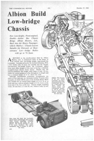
New Low-height, Front-engined, Double decker Bus Chassis Brings Albion Motors, Ltd., Back into the Heavy Passengervehicle Market : Chassis Layout Suitable for Forwardor Rearentrance Low bridge Bodies
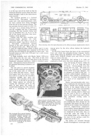
with up to 74 Seats ARETURN to the double-decker field by Albion Motors, Ltd., is announced today in the .shape of an entirely new, low-bridge design, type-named the Lowlander. Intended primarily for forward-entrance, 30-ft. x 8-ft. bodies with 72 seats, but suitable also for 74-seat, rear-entrance, low-bridge bodies, the Lowlander differs from most other designs of this type in having a relatively straightforward chassis frame layout. Despite this, the entrance-platform step height when laden is only 15} in., whilst the central gangway is flat throughout its length and has a constant height of 17 in. above the road.
Although conventional suspension arrangements are used at front and rear, an Alexander-bodied 72-seater (two examples of which will be seen at the Scottish Motor Show next month) has an overall laden height of 13 ft. 3+ in. at front and rear, and an unladen height of 13 ft. 4+ in. at the front and 13 ft. 6 in. at the rear. Chassis weight, including water, oil and fuel, is 5 tons 81 cwt., which is only 2+ cwt. above that of a Leyland Titan PD3, and 31 cwt. less than that a a Leyland Atlantean. The Lowlander's gross weight rating is 13 tons 4 cwt., with a rear-axle limit of 8 tons 8 cwt.
To a greater degree than hitherto, there is evidence of considerable co-operation between Albions and Leyland Motors in the make-up of the Lowlander. The engine, hydraulic coupling, gearbox, front axle, steering gear and frontal panelling are all used in various Leyland models, whilst the special rear axle is a Leyland assembly also.
As a result, Lowlanders can be introduced into a fleet of vehicles already containing Titans, say, without presenting detrimental non-standardization effects—despite the big differences in overall chassis layout—whilst a further big advantage in this respect is that the layout of the Lowlander chassis as far back as the rear of the front springs follows almost exactly that of the Titan except that the driving position is some 3 in. lower.
The standard engine for the Lowlander is the Leyland 0.600 Power-Plus 9.8-litre six7cylindered diesel, the ratings of which are 140 b.h.p. (net) at 1,700 r.p.m. and 438 lb.-ft. torque at 1,200 r.p.m. Unless otherwise specified, the engine carries a Leyland 18-in.-dia. fluid coupling incorporating a centrifugally operated lock-up clutch, which engages fully at 1,100 r.p.m. Alternative to this is a 161-in.dia., single-dry-plate clutch for use when the optional synchromesh gearbox is fitted.
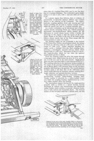
From the coupling output the drive line passes through a three-gear train, which lowers the drive by 8 in. and offsets it to the near side by the same amount. Single-helical gears are used, and these effect a ratio step-up of 0.857 to 1. The resulting reduction in the maximum torque available at the output of this gearing is deliberate in that it permits the use of Hardy Spicer 1510 universal joints on the two-piece propeller shaft leading to the gearbox. The overall diameter of these joints is less than that of the 1600-series joints which would otherwise be necessary, thereby assisting floorheight reduction and ground-clearance increase.
The engine-and-coupling unit has a four-point mounting, incorporating Leyland rubber-bushed swinging links. Torque reaction is absorbed by a rubber-bushed torque arm below the coupling housing, supplemented by a twoway rubber snubber above the housing.
The intermediate support bearing for the engine-gearbox propeller shaft is carried in a special bracket recently developed by Albions and incorporating four Metalastik rubber bushes which combine to provide vibration insula tion in both vertical and horizontal planes. The forward section of this two-piece shaft has a splined joint, and this is at the rear end of the shaft so that its minimum diameter occurs-Where the shaft passes through a hole in the third chassis cross-member.
The standard gearbox is a Leyland Pneumo-Cyclic four-speed, semi-automatic unit, with electro-pneumatic shift, the short control lever being outrigged from the left of the steering column. The box provides forward ratios of 4.28, 2.43, 1.59 and 1 to 1, reverse being 5.97 to 1, and the complete unit has a three-point mounting, the box location being such that its centreline lies 1 ft. 61 in. to the left of the chassis centreline, thus maintaining a level gangway_ Chassis with the fluid coupling and Pneumo Cyclic gearbox are typenumbered LR.1, but there is to be an alternative model—type LR.3—which has a four-speed synchromesh gearbox located in the same position as that of the Pneumo-Cyclic unit. When this box is used the single-dry-plate clutch is fitted, and it is controlled by a conventional lever mounted to the left of the driving seat and linked to the gearbox by three rods. The forward ratios are 4.95, 2.63, 1.59 and 1 to I, with reverse gearing of 4.6 to I.
A single propeller shaft with Hardy Spicer I 600-series joints drives into the rear axle. The front of this shaft carries a pulley for the single V-belt drive to the Tecalernit Syndromic automatic lubricator, which is standard equipment. Alternatively,CIayton Dewandre air-operated lubricating equipment can • be fitted.
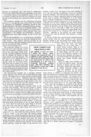
The rear axle is a special droppedcentre, double-reduction assembly, the top of the centre tube of which lies 5i in. below the hub centres. Spiralbevel gears form the primary reduction (2.44 to I) and for the secondary reductions straight spur gears are employed. The centreline of the axle input is 13 in. to the left of the chassis line. Ratio options are effected by varying the reductions given by the pairs of spur gears, the choice of overall ratios being 4.64, 5.03, 5.49 and 6.00 to 1, including the 0.857-to-1 step-up given by the drive off-set behind the hydraulic coupling.
An H-section beam forms the basis of the conventional front axle which has phosphor-bronze king-pin bushes, thrust being taken by hardened steel buttons. The front wheels carry 10.00-20 (14-ply) tyres and 9.00-20 (12-ply) twins are used at the rear_ Shot-peened, semi-elliptic leaf springs 4 in. wide are employed at both axles, the front springs being 4 ft. 2 in. long and having 10 leaves, whilst the rears are 5 ft. 2 in. long and have 14 leaves. Chrome-plated, 14--in.-dia. spring pins arc used. The front suspension is controlled by Armstrong DAS.I2PXP lever-type dampers, but no dampers are fitted at the rear. A Leyland rubber-bushed stabilizer, as fitted to Titan chassis, is incorporated, however_ A future development will be a form of air suspension for the rear axle.
Marks cam-and-double-roller steering is employed, the steering box itself being a special iron casting mounted directly to the chassis frame at the same point as the front cross-member and front spring-hanger bracket. A 22-in.-dia. steering wheel is fitted and the box ratio is 28.5 to 1, giving 4.? turns of the wheel from lock to lock. The calculated turning circle is 65 ft. 6 in.
Westinghouse split-circuit air-pressure braking has been chosen for the Lowlander and power for this is provided by an air-cooled, twin-cylindered, 10-cu.-ft., engine-driven compressor. S-cam brakes, almost identical to those fitted to the Leyland Atlantean chassis, are employed at both axles: they are 15i-in.-dia. units, the width of the front linings being 5 in., whilst that of the rears is 8 in., giving a total frictional area of 702 sq. in_ The brakes are actuated through Bendix-Westinghouse worm-type slack adjusters by diaphragm units, with 20-sq.-in. diaphragms for the front brakes and 24-sq.-in. assemblies for the rear.
An unusual feature of the handbrake system is that it is air assisted, possibly the first time that assistance has been applied to the handbrake of a production British passenger chassis.
The handbrake linkage, and the mechanical advantage given by it, is virtually the same as that of the Titan chassis, so, unassisted, the handbrake retardation should be com parable with that of the Titan, thus should meet the requirements of Ministry of Transport Certifying Officers. The system is similar to that incorporated in Leyland PowerPlus heavy-duty goods models, with a pull-type brake valve incorporated in the roddage and controlling a 24-sq.-in., diaphragm-type servo acting directly on one of the relay levers.
Air for this handbrake servo is drawn from an entirely separate reservoir from the two reservoirs feeding the foot brake circuits. This auxiliary reservoir provides air for gearbox actuation also, and tappings would be taken from it for any air-operated body equipment, such as door-operating rams.
The handbrake linkage acts on the rear-axle brake levers through a novel form of cross-shaft—mounted on the rear of the axle casing—which incorporates a principle adopted some years ago by Albions on certain of their goods chassis, but since dropped. The pull lever is at the right-hand side of the shaft and is attached to a tube through which the cross-shaft passes. This outer tube is welded to the centre of the cross-shaft, thus the brake pull is transmitted to the centre of the shaft, thereby eliminating any wind-up which could lead to braking unbalance, albeit of a minor nature.
The chassis-frame assembly has a one-piece channelsection pressing at the off side, the material thickness being 9/32 in. The flanges are 3 in. wide, and the maximum depth between the axles is 81 in. Additional inter-axle strength is provided by a 73-in.-deep, 3-in.-thick flitch plate, which runs from the front-spring rear hanger bracket to the start of the kick-up over the rear axle, this kick-up rising 1 ft. 34. in. above the level of the inter-axle section.
Three 9/32-in. channel-section pressings make up the near-side main framing. The rear-most section is similar in shape to the equivalent part of the off-side member as far forward as the rear-spring front hanger bracket, forward of which bracket it sweeps outwards slightly and terminates at the pressed cross-member immediately behind the gearbox.
In the same way, the forward main member takes the same section as that of the off-side side member as far back as the front-spring rear hanger bracket. In this area the frame drops down sharply so that its upper flange lies 1 ft. 11 in. below the level of the upper flange at the front end, and at the same time the depth is reduced to 53 in. so that the height of the upper flange above ground level is 163 in.
This reduced section extends rearwards for approximately 4 ft. 3 in., after which the depth gradually increases to 81 in., whilst, at the same time, the member sweeps outwards to pass outside the gearbox, the top and bottom flanges being tapered away towards the end of the member. The intermediate side member runs froin the frontspring rear hanger bracket to the rear-spring front hanger bracket, and has its flanges facing outward. In the vicinity of the doorway, where the depth of the forward inner member is only 53 in., the depth of the outer member is 7 in., the two members combining to form the required structural strength. The forward inner member cannot be deeper than it is without raising the platform height because of the need to comply with Regulation 8 of the Public Service Vehicles (Conditions of Fitness) Regulations, 1958, which demand a ground clearance of 10 in. rearwards for a distance of 13 ft. over a width on each side of the vehicle centreline of not less than one-third of the front-axle track.
Behind the doorway area the depth of the outer member increases to 81 in., and after a slight rise it then runs horizontally to its end, the height of the upper flange above ground level being 193 in., compared with 143 in. at the doorway. Adjacent to the gearbox the outer member is back to back with the forward inner member, to which it is bolted.
To the rear of this area a special boxed, inverted top-hat section bracket links the outer member to the rearmost member, bolting to the rear-spring front hanger bracket. Forward of the gearbox and to the rear of the entrance area, where the inner and outer members are 12 in. apart, there is a simple boxed bracket, whilst at its forward end the outer member has a different type of box bracket welded to its upper flange, and the inner side face of this bracket is bolted to the forward inner member, the deep casting which provides the near-side, frontspring, rear hanger bracket being interposed.
There are eight cross members, allof which are bolted in place. The first member is tubular and lies ahead of the engine. Behind the engine there is an arched H-section member, and these two members tie the frame together at the front and rear of the front springs, in addition to supporting the engine. The third cross member is a pressing, and the fourth is a cranked tube, this lying ahead of the gearbox. The member immediately behind the gearbox is another pressed channel, and at the front of the rear springs there is a cranked tube, with a light, pressed channel at the rear of the rear springs. At the end of the frame there is a 7-ft. 53-in.-wide channel.
Three inter-axle outriggers arc provided on the off-side and near-side. No rear frame extensions are offered, body builders being expected to cantilever their framings rearwards of the end of the frame.
The twin fuel tanks are located on the off-side of the chassis frame, these tanks being similar to those employed on the Leyland Affantean and providing a total capacity of 38 gal. There is a single filler—with magnetic cap—on the forward tank.
The Lowlander has 24 v. lighting and starting equipment, power for which is provided by a 7-in.-dia., 55-amp. dynamo. C.A.V. equipment is standard and, instead of the standard D.C. dynamo, an A.C. generator can be specified.
The standard front-end panelling is almost identical to that used by Leyland's on their latest Titan models. It has glass-fibre bonnet, front panel and radiator grille, steel wings and inner engine cowl, and cast aluminium-alloy floor plates, all mounted on a steel sub-frame.
The Lowlander will be seen on the Albion stand at the Scottish Show as a complete vehicle, with a 72-seat body built by Walter Alexander and Co. (Coachbuilders), Ltd. It will be finished in the livery of Western S.M.T. Co., Ltd.: the other Lowlander exhibit will be on the Alexander stand, and will be a similar model but in Glasgow Corporation livery.