


A New C.A.V. Injection Scheme
Page 36
If you've noticed an error in this article please click here to report it so we can fix it.
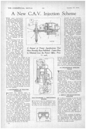
THE usual variable' delivery injection pump, supplying fuel through pipes to the injectors, is unsatisfactory in some circumstances owing to elastic deformations in the pipes and the generation of pressure waves therein. Such are the views of C.A V., Ltd., and W Nicholls, both of Warple Way, London,
W.3 These inventors disclose, in patent No. 563,787, a novel method of fuel injection.
The metering of the fuel and its injectioh are performed by two separate mechanisms, both at which are shown in the drawing. The metering pump (1) is, operated by a swashplate and is provided with a number of plungers (2) which pump the fuel into the individual pipelines, at a pressure much below that needed for injection. The pump is controlled for output in the usual manner by rotating the plunger sleeves, which, in this case, are united by gearing. An external control (3) can adjust the gearing and is the equivalent of the conventional rack-rod.
The output from this pump is piped . to the separate injectors which, in this system, perform also the duty of stepping-up the pressure. The measured fuel is forced through pipe 4 and lifts a short plunger (5) through a distance proportional to the volume of the charge. Above the plunger is a space (6) which is kept full of rubricating oil under slight pressure from inlet 7. As the plunger (5) is lifted, some of the oil is displaced from space 6 and driven back into the supply. At the required moment, a long plunger (8) is forced downward by a cam (9) and the fuel is, thereby, injected through the nozzle into the cylinder.
A REFINEMENT IN TRACTOR STEERING •
pATEINIT No. 563,719 refers to tractors having one steetable front, wheel and two driven rear wheels, and describes a means for assisting the steering action to perform sharp turns by selectively braking the driving wheels. The patentee is H. Lambert, St. Joseph, Michigan, U.S.A.
In the tractor described, the brakes are normally worked by hydraulic pressure from a master cylinder The improvement consists in the provision of a valve which can shut off the braking fluid from either wheel, and this valve is operated by the steering mechanism For small locks, no braking occurs, but during a large lock an electric contact on the steering gem causes the valve to shut off one or other of the hydraulic lines. If the brakes be then applied, the steering action is amplified by the drive oh one side. SELF-CHARGING A TWO-STROKE ENGINE
iT is known that the combustion product s of a two-stroke engine, after issuing from the exhaust port, create, by virtue of their momentum, a partial
vacuum in the cylinder. But as this state may persist for only as little as I/1,000th of a second, it is difficult to make use of the momentary suction. To trap the vacuum by means of a quick-acting valve, so that it may be used to assist the incoming charge, is the object of a scheme shown in patent No. 563,656, by A. Nesfield, 65, Fordhook Avenue, London, W.5.
The drawing shows a sec. tion of the proposed engine, into which the charge is admitted via an overhead inlet valve (1) and descends info the cylinder while the exhaust gases are making their exit from the pistoncontrolled port (2). The essence of the invention is the provision of a poppet valve (3) in the outlet; this is operated by a special snail-cam (4), which gives a snap-action closure at the moment when the vacuum is highest. By this means, it is claimed, a moderate degree of supercharge may be obtained.
-The exhaust-valve timing has to be varied with the speed of the engine, and to attain this the camshaft is fitted with an auto-advance mechanism.
AN INEXPENSIVE ENDLESS TRACK WHILST cost is not a primary con VV sideration in he design of military vehicles, it is of • great importance in normal spheres of use, and, with this in view,a design for an inexpensive endless track is disclosed in patent No. 563,628, by F. Burgess, Geneva, Illinois, U.S.A.
The drawing shows a unit of the tread, in which a pair of tubes (1) is gripped between a lower plate (2) fitted with strakes (3), and an upper member (4), which has a bonded-on 'rubber pad (5). The strakes engage the ground whilst the rubber pad makes contact with the idler wheels of the vehicle, also rubber-covered A SIMPLE TOP-DEAD-CENTRE LOCATOR I T is often a problem to find the too dead-centre position of a piston, especially in engines in which it is difficult to insert a wire through the sparking-ping hole. Even then, unless the valves he visible, it is' difficult to determine whether the compression or exhaust stroke has just occurred. A simple and ingenious suggestion is made in patent -No. 563,913, by IL Lodge, 50, Birkhouse Lane, 1VIoldgreen, Huddersfield.
This inventor proposes to employ a .sensitive whistle adapted to screw into the sparking-plug hole. By turning the engine slowly, the whistle would indicate the top of the compression stroke by ceasing to sound