


Influence of Combustion-space Design on Oil-engine Efficiency
Page 22
Page 23
Page 24
If you've noticed an error in this article please click here to report it so we can fix it.
By j. Pickles
THE attainment of the present standard of oil-engine efficiency has been reached only after a vast amount of experimental work, and research workers are seeking to improve performance still further and are endeavouring to discover the answers to many questions. Few operators interest themselves in the intricate processes occurring in the engine cylinders, having, no doubt, continually before them the necessity of extracting a reasonable profit from their vehicles,
There is, however, a vast amount that is interesting in the functioning of the oil engine, and to comprehend the reason for the diversity of designs now offered, and to assist in the choosing of a new engine, certain of these fundamentals must be :understood.
The combustion of oil fuel is a complex process which is a combination of two hypothetical methods. The first requires fuel to be burnt in a cylinder containing a piston capable of maintaining a constant reaction. A vertical cylinder with the open end uppermost and containing a weighted piston is a suitable mechanism : as the fuel burns in this device a Constant pressure is maintained in the cylinder. The other method is known as the constant volume system, whereas the first is termed the constant pressure, and combustion must occur in an unvariable space so that a high pressure rise will result.
Difficulty of Attaining the Ideal
In theory, 'the most efficient burning occurs under constant-volume conditions but, in an actual engine, such a condition is simulated only at or near T.D.C. and, as the combustion process is spread over a number, of degrees of crank motion, the time factor, alone, precludes attaining this ideal form of combustion.
The fluctuating nature of the load, the heat losses and several other factors also' prevent constant-pressure burning so that, in practice, a combination of the two occurs.
With this brief description of the hypothetical case fully grasped, it is now 'necessary to follow the process of oil burning in the engine. On the induction stroke air i.-. drawn or inspired into the cylinder and then compressed to a fraction of its original volume, ranging from about 1-10th to 1-16th, thereby increasing its pressure and temperature. During the compression stroke oil is injected into the combustion space, where, after a short period, it commences to burn. This lag, which is termed the delay period, is of the utmost importance in oil engine design, as will be shown later.
Following this, a rapid spread qf combustion takes place throughout the cylinder, and this is termed the flamespread period. The third, and final phase, is the direct-burning period when the fuel, which is stilt being injected, burns on entry. This is the only part of the combustion process directly controllable as it is mechanically limited by cutting off fuel delivery.
These three periods must now be considered in greater detail. The delay period has been the subject of some speculation, one theory being that each minute fuel droplet is heated by contact with the hot air in the combustion chamber and the outer surface of the droplet vaporizes and commences to burn. The nucleus thus las its temperature increased still further by the surrounding envelope of flame and the burning continues until combustion is completed. Calculation, however shows that there is insufficient time for complete evaporation and, further, the more volatile fuels are not so suitable for oil engine use.
A more popular theory is that the ignition of the surface molecules of the droplet increases the heat of the nucleus which, after combination with oxygen, forms peroxides which decompose, in the process of which great heat results and the whole of the nucleus is consumed. The motion of the droplet past the air, or vice versa, speeds up the process of combination of oxygen and fuel.
Rapid Burning Minimizes Engine Knock Under the conditions of high temperature and pressure existing in the cylinder of a well-designed engine, the fuel would be consumed without undue vaporization but, if the burning be delayed so that an excessive degree of vaporization o c c ur a, spontaneous ignition, with a tremendously rapid pressure rise, will be instigated, resulting in the sound referred to as Diesel knock. This condition, although resembling, in effect, the detonation which occurs in a petrol engine is different in that, in the latter case, it occurs as the result of ultra high-speed " end burning" whereas, in the oil engine, it is the first stage in which the knock is prevalent. It is, therefore, important that burning should take place rapidly in order to minimize vaporization.
If the delay period be unduly long the ignition must be instigated comparatively early on the upstroke so that, although the pressure rise is very small in this phase, it operates in a reverse direction to that required. Further, the quantity of fuel burnt under constant volume conditions will be reduced, with consequent effect on the specific fuel consumption. The quantity of fuel in the cylinder at the commencement of flame spread will depend on the extent of the delay action as fuel is, of course, being injected continuously during and after this phase, so that the smoothness of running will be improved by a short delay as the pressure rise will be smaller, In contradistinction, the more fuel contained in the cylinder during the flame period the greater will be the quantity burnt under constant volume conditions, and the higher will be the thermal efficiency, so that, in practice. a compromise must be struck between smooth running and good fuel consumption.
An important influence in the length of the delay period is the density of the air so that, as an increase in the air pressure has a beneficial effect, every effort should be made to minimize piping and valve resistance losses. Supercharging has, consequently, the effect of reducing the delay period end' has an advantage not found in normal petrol engine in which, assuming the engine to have bearings of such size that only a reasonable safety margin exists, an increase in supercharge would overload the rubbing surfaces.
In the case of the oil engine, however, the reduction in delay, resulting from the increased induction pressure, does not give so great an increase in the maximute pressure whilst materially increasing the b.rn.e.p., and, incidentally, smoothing the power delivery.
In a theoretical cycle the delay period would occupy the same time, in seconds, at all engine speeds and a more unsatisfactory combustion process would ensue at the higher engine speeds. But in the actual engine important modifications exist. The heat loss is reduced with increased speed owing to the reduced time and, as already shown, increased temperature reduces the delay. Also, as the engine speed increases the fuel injected, per degree of crankshaft rotation, becomes less so that the fuel in the cylinder at the moment of injection is uot so great at low speeds,
Combustion Head Shaped to Create Swirl
During the delay period and continuing until the end of injection, fuel is being forced into the cylinder. In ideal conditions this spray will just reach the wall of the combustion chamber and so pass tkrough the maximum quantity of air. At high speeds, however, the time available for the pamge of the fuel across the chamber is very short and the chamber, therefore, must be as compact as possible to reduce the injection pressure to its minionum. During the passage through the dense, hot air, the friction, of the passing spray reduces the fuel to a globular condition, suitable for combustion. A. factor which materially improves the distribution of these droplets through the chamber is swirl or turbulence.
Turbulence has become a, familiar word to users of oil engines, but the attainment of air movement in its several• forms is a problem in itself. Fuel sprayed into a cylinder is quite valueless unless it be able to combine with oxygen so that, for efficient combustion, this must be arranged by taking the oil to the air, or the air to the oil, or a combination of both. The compression of air inside the engine cylinder requires mirk to be done at the expense of power output so that, for a given output, the minimum possible air is required.
It is obviously impossible to distribute a quantity of fuel amongst a theoretically correct quantity of air and to ensure that each fuel molecule combines with the requisite number of oxygen molecules, so that a quantity of air greater than the theoretical must be introduced. The percentage of air excess will depend on the quality of the design, and the engine having the best air utilization factor will have the highest output: consequently, the manner in which the air and fuel are mingled is of vital importance.
Engines have been produced in which no attempt at organized air movement has been made, reliance being placed on -the injector, to atomize the fuel. This method requires minute fuel delivery orifices and high pump pressures to obtain the desired end with risk of stoppage as the result of carbon
particles or particles suspended in the fuel choking the injector nozzles.
The best modern examples adapt the principle of taking the air to the fuel by means of air swirl, and a great deal of work has been done in the search for the most satisfactory manner of accomplishing this. As previously mentioned, any form of air movement demands power, no matter how small it may be, at the expense of the output of the engine, and as the movement of heated air results in temperature loss to the surrounding cool areas, the minimum of movement is the aim.
How a Turbulent Effect is Promoted
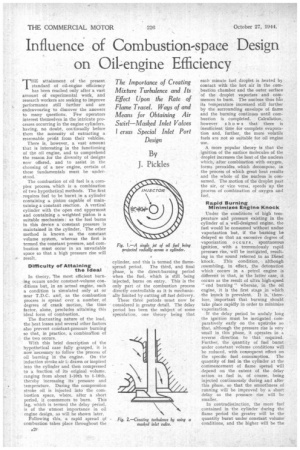
In its simplest form turbulence is required to sweep away the burning eiroplets issuing from a fuel jet and to feed a constant supply of oxygen to the new droplets, so that fuel is not sprayed into an area where the combustion process has impoverished the store of oxygen. This is accomplished by revolving the air in the cylinder past an oil spray directed across the path of rotation of the air stream.
In Fig. I a single jet is represented as being projected radially across a cylinder. To bring all the air in contact with the fuel the air stream must make one rotation. If more than one revolution occurs burning fuel will pass • through the jet, and the last part of the fuel spray will enter a zone which is deficient in oxygen, If two jets be used "diametrically opposite then the turbulence will require to be only half as rapid as when a single jet is employed and, assuming identical conditions, four jets will halve this speed.
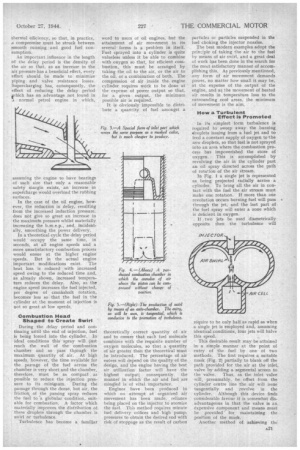
• This desirable result may be attained in a simple manner at the point of entry of the fuel by one of two methods. The first requires a suitable mask (Fig, 2) partially to blank off the path provided for the air at the inlet, valve by adding a segmental screen to the valve. Thus, as the inlet valve will, presumably, be offset from the cylinder centre line the air will issue' tangentially and revolve in the cylinder. Although this device finds considerable favour it is somewhat disadvantageous in that the valve is an expensive component and means most be provided for maintaining the position of the mask.
Another method of achieving the desired swirl is to so shape the inlet port that a portion of the outlet area, corresponding to the area occupied by the mask in the first scheme, is starved, thereby achieving the same result in a less expensive'-manner (Fig. 3).
The provision of a mask to the inlet valve would appear to restrict the incoming air supply, but this is, in actuality, only true to a small degree, and by careful design the required swirl speed can be obtained within fairly close limits.
Some engines employ a pan-shaped combustion space formed either in the piston crown or in the cylinder head, which latter has a diameter somewhat less than that of the cylinder bore— often about half, This diameter and depth are influenced by the combustion conditions, but an important result is that the air which is set in motion during entry is almost entirely contained in the combustion chamber at T.D.C., with the result that its speed, in angular measure, is increased.
Reducing Oil DilutEon Thus, the induction swirl need only be a fraction of that required for complete fuel-air mixture with an obvious improvement in thermal and volumetric efficiency. A subsidiary
• advantage of induction swirl is that the layer of stagnant gas which tends to cling to the cool cylinder wall is swept away, which has the effect .of reducing dilution of the lubricant.
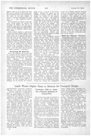
Still considering the pan-shaped combustion chamber, regard the annulus of air above the top face of the piston to be compressed without being able to change position and. similarly, the centre core above the combustion cell (Fig. 4). For simplicity, a wall of extreme thinness will be imagined to separate tl c two volumes and; as an example, let us consider the chamber
depth to be a quarter ot the stroke length. Moving the piston up the cylinder a distance equal to half the stroke, the volume of the annular cylinder will be halved. The length of the centre core will, at starting, be 5/4ths that of the annulus and, at half stroke, the volume will have changed 3/5ths to that of the original. The pressure will thus be less in the centre. core than in the annulus, a condition that would obviously be impossible in an actual cylinder, so that an inward flow of air will occur, This flow will have an appreciable velocity only towards the end of the stroke, at which time fuel is being injected.
The flow thus instigated moves radially inwards 'until, at the centre, balance occurs, and the air is repelled outwards after first being directed downwards. If a section of a cylinder could be examined the air flow would be seen to be approximately circular, depending on the shape of the combustion chamber. Some engines incorporate cylinders having a recess of such shape as to permit of a streamline rotation but. as the overhanging lip somewhat reduces the scavenge efficiency, this is not often used.
Considerable turbulence is caused by the " squish " and material benefit may be derived from it during the combustion process. The width of the top band and, consequently, the ratio of the volumes of annulus and core, obviously will determine the inflow velocity, as does the form taken by the piston top face. Any sizable chamfered corner of the chamber would reduce the " squish " velocity.
Air swirl may be induced on the compression stroke by methods other than " squish," which is invariably employed only to augment the induction swirl at the. required moment. Compression swirl is obtained by transferring air, during the compression
stroke, to a suitable chamber situated either in the cylinder head or piston, in such a manner that its entry is tangential. Tile transfer or antechamber may be either cylindrical or spherical and the connecting throat of a single OT multi-hole type.
A device which is sometimes employed to augment the swirl at the end of the stroke is some form of extension on the piston. This extension enters the throat and reduces the cross sectional area while, at the same time, it allows of a large area and, therefore, a free flow during the major part of the stroke.
Swirl by "Squish" Process Compression swirl may also occur in a cylindrical chamber arranged with its axis and that of the throat coincident with the cylinder centre line in a similar manner to the " squish " process. As the air is pushed through the throat it impinges on the extreme wall and turns out radially so that, if examined in cross-section, we have the toroidal flow as with "squish."
Lastly, swirl may be achieved during the combustion process by using an ante-chamber. Fuel is burnt in this subsidiary chamber, which usually contains some 50 per cent. of the total air. The resulting expansion causes a rapid stream of fuel and air, separately and in combination, to issue from the cell into the cylinder where tangential entry causes a rapid swirl (Fig. 5).
One well-known unit employs a chamber of figure-eight form in. the piston head. The ante-chamber communicates with this space at the junction of two cylindrical divisions and the injector is directly opposite. Thus the rapid stream of air issuing from the ante-chamber sweeps away the fuel from the injector and, in, the rapid double swirl which ensues, intimate
.association occurs. '