


Actuating Valve Tappets Hydraulically
Page 74
If you've noticed an error in this article please click here to report it so we can fix it.
A HYDRAULIC tappet assembly is r-k described in patent No. 821,755. (Ford Motor Co., Ltd., 88 Regent Street, London, W.I.) The tappet shown in the drawing operates thus: oil from the lubricating system is pumped into the crosshole (1) and passes through the central space to reach a one-way valve (2). This admits the oil to . the bottom space, forcing the Sliding member (3) upwards to take up the slack.
The air excluder which is the main object of the patent comprises a disc (4) placed in the path of the descending oil. The disc is perforated around its edge so that the oil passes through it in an annular stream which adheres to the walls. Any air trapped in the oil supply remains in the upper space because the stream is too thin to carry bubbles.
PARALLEL-LINK SUSPENSION
PATENT No. 820,921 shows a parallel-link suspension layout claimed to be free from lateral forces arising from vertical movement. (F. POrsche, Porsche-Strasse, Stuttgart-Zuffenhausen, Germany.)
In this design the pivot axis of the upper link is inclined with respect to the lower one. The drawing shows a frontal view in which the axes of the lower links (1) lie parallel with the road. The upper links, however, have their' axes inclined to each other at an included angle of 140-150 degrees. In this case the angle is 143 degrees.
The geometric result of the layout is to shift the instantaneous centre about which the wheels swing to a point above road level. In the-normal system, this centre usually lies on the surface of the road. The resilient members in this suspension system are torsion rods (2) housed in tubes (3).
PETROL INJECTION PUMP CONTROL A CONTROL scheme for petrol-in jection systems is the subject of patent No. 821,729. It provides a means of adjusting idling 'output without disturbing the full-load setting. (The S.U. Carburetter Co., Ltd., Wood Lane, Erdington, Birmingham, 24.) • The diagram shows the bellows unit (1) which senses the pressure drop between two large pipes (2 and 3) connected to different points in the air a34
-ntake. In the idling condition, these arge pipes are closed by cocks (4), so that the capsale. is then subject to pressure only via a by-pass (5), a small bore pipe (6) and the venturi (7).Adjustment for idling cart then be made by turning an air-bleed
screw (8). —
When the throttle is opened, the two cocks arc opened too by the connecting linkage and in this condition the action of the small-bore pipe system ceases to be important. This means that idling adjustments have no effect on the cruise and full-load settings.
It 47
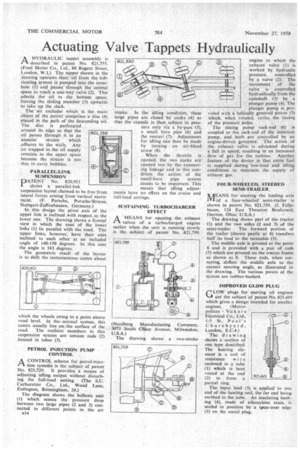
SUSTAINING TURBOCHARGER EFFECT A MEANS for opening the exhaust valves of a turbocharged engine earlier when the unit is running slowly is the subject of patent No. 821,799.
(Nordberg Manufacturing Company, 3073 South Chase Avenue, Milwaukee, U.S.A.) The drawing shows a two-stroke engine in which the exhaust valve (1) is worked by hydraulic pressure, controlled by a valve (2). The movement of the valve is controlled hydraulically from the camshaft (3) by a plunger pump (4). The plunger pump is provided with a helically grooved piston (5) which, when rotated, varies the timing of the pressure pulse.
The timing pump rack-rod (6) is coupled to the rack-rod of the injection pump, and both are controlled by an engine-driven governor. The action of the exhaust valve is advanced during a fall in speed, resulting in an increased flow of gas for the turbine. Another feature of the device is that extra fuel is -supplied during low-load and idling conditions . to maintain the supply of exhaust gas.
FOUR-WHEELED, STEERED SEMI-TRAILER AEANS for steering the leading axle IVI of a four-wheeled semi-trailer is shown in patent No. 821,330. (J. Fellabaum, 124 East Thruston Boulevard, 'Dayton, Ohio, U.S.A.) •• '
The drawing shows part of the tractor .(1) and the two axles (2 and 3) of the semi-trailer. The forward portion of the trailer (shown partly at 4) transfers half its load to the turntable (5).
The middle axle is pivoted at the point 6 and is provided with a pair of rods (7) which are pivoted on the tractor frame as shown at 8. These rods, when cornering, deflect the middle axle to • the correct steering angle, as illustrated in the drawing. The various pivots of the system are rubber-bushed.
IMPROVED GLOW PLUG
GLOW plugs for starting oil engines are the subject of patent No. 821,601 which gives a design intended for smaller engines. (Metropolitan Vic kers Electrical CO., Ltd„ 1-3 St. Paul's Churchyard, London, E.C.4.)
The drawing shows a section of one type described. The heating element is a coil of resistance wire enclosed in a tube (1) which is bent round at the end (2) to form a partial ring.
The input lead (3) is applied to one end of the heating coil, the far end being earthed to the tube. An insulating bushing (4), made of ethoxylene resin, is sealed in position by a spun-over edge (5) on the metal plug.