


A FLOATLESS CARBURETTER.
Page 72
If you've noticed an error in this article please click here to report it so we can fix it.
A Résumé of Recently Published Patents.
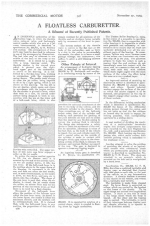
AN INGENIOUS carburetter of the floatless type, in which the throttle valve, extra-air valve, and fuel-supply control needle—which also acts as a jet —are interconnected, is described in specification No. 205,411, by H. Rothery and another. The arrangement of these parts may best be described in reference to one of the accompanying illustrations. The fuel inlet may be observed in the middle of the base of the body of the
carburetter. It is closed by a needle with a long, tapering point.. The throttle shutter is the curved piece which is pivoted near the righthand upper part of the carburetter, as shown in the 'drawing. Itis controlled by a Bowden-type wire, working in conjunction with the compression spring shown. The needle tends always to close the jet orifice, being impelled to do so by a light spring, which is not shown on the drawing. On the left is the air shutter, which opens and closes in accordance with the engine suction. On the shutter, is pivoted a lever, which does duty as a cam, its curved under surface being designed to work in conjunction with the pin at the lower end of a bell-crank lever, which is also
Bowden-wire cent-roiled, The npper stirface of this same cam fever engages a collar on the jet needle.
In action the engine suction operates to lift the air shutter until it is arrested by the end of the throttle valve. As the air shutter moves, it lifts the cam lever. If the bell-crank lever is in the position shown in the upper figure of the drawing, its movement is an idle one, and does not affect the fuel needle, and, in such circumstances, as the needle is down, no fuel flows, and pure air is drawn into the cylinders. The shape of the cam lever is such that, when the air shutter is closed, the jet needle closes the orifice, no matter what may be the position of the bell-crank lever, so that there is no need for a float chamber.
Movement of the bell-crank lever alters the position of the fulcrum upon which the cam lever turns. As shown in the lower figure, the needle is lifted the maximum amount, and the mixture will be correspondingly rich. It is claimed that, with the bell-crank lever in any position, the proportions of fuel and air 036
remain constant for all positions of the throttle and air shutters, being variable only by movement of the lever in ClUeb
The bottom surface of the throttle valve is convex to the flat face of the body of the carburetter, and, as there is a slot in the valve to accommodate the needle the effect is to leave a small passage through the carburetter ;this suffices to allow a slow-running•mixture to pass.
Other Patents of Interest.
An arrangement of hydraulic tipping gear is described in specification. No. 205,450 by II. Burkhardt and another. It is interesting manly by reason of the
provision for universal attachment of the ram to the body of the vehicle, and the hydraulic cylinder to the chassis, Both these connections are of the ball-andi socket order, that of the cylinder emi bodying such provision for packing of the joint between the ball and its socket that the need for any flexible piping to convey the working fluid is obviated. The design also incorporates a safety device to limit the movement of the ram, For its operation, advantage is taken of the fact that, as the body of the vehicle is tipped, the ram and cylinder must tilt, and a special collar on the outside of the cylinder is made to contact with plungers which open valves in the circulating system of the fluid, to liberate the pressure and prevent ftuther movement of the ram. The gear is designed to operate a three-way tipping wagon.
An ingenious brake gear is described by B. Brown, in, specification No.
205,334. It is operated by rotation of a central sleeve, which is coupled to floating shoes by toggle mechanism.
• The Timhen Roller Bearing Co. state, in the course of a preamble to specification No. 205,306, that in connection with roller bearings it is impossible to obtain such precision and uniformity of •construction as to ensure that the loada are uniformly distributed over all the constituent parts of the bearing. In consequence, -failure may occur because seine of the rollers are overloaded and therefore chip off at the ends. The patentees propose to make the rollers in such a manner that the end portions do not immediately come into contact with the races, and, as a means to that end, form them, near each end, with surfaces which make slight angles with the main surfaces of the roller, the effect being the same as a very gradual taper.
An improved method of mount'ng an observation mirror is described in specification No. 205,292 by Joseph Lucas, Ltd., and others. Special indented washers engage the surfaces of the part to which the mirror support is to be fastened, and projections on the clip of the support engage other notches in one of these washers.
In the differential locking:mechanism which is described in specification No 205,267 the bosses of the differential -pinions project through the casing, and are cut away se. that the fiat surfaces so formed may be made to engage for locking purposes, with corresponding apertures'in a sliding sleeve.
A neat method of dividing the crankcase of a multi-cylinder two-stroke engine into "airtight compartments has been in.vented by the Low Engineering Co., Ltd., and is patented in specification No. 205,333. Each bearing cap has projecting ribs, which., make contact with resilient parking which is embedded in the crankcase cover.
Another attempt to solve the problem of providing the wheels of an agricultural tractor with withdrawal cleat's which are permanently attached to the tractor is described in specification No. 205,241 by T. H. Evans. The cleats are attached to an eccentric which is mounted on the hub and is manipulated by a hand lever.
Specification No. 198,468, by F. E. Ellis. describes a combined turntable and tipping gear, so designed that tipping mi.y take place to each side, to the rear
intermediate direction. the vehicle, or in any direction. A circular bracket is secured to the chassis of the vehicle, and within this a turntable may revolve. • The turntable is made from channel steel. Its lower flange is supported on rollers, which are carried by the bracket on the frame of the chassis. To its upper flange are secured two longitudinal bearers. A shaft at one end of these is the hinge about which the body is tipped. At the other end the tipping gear is carried. The turntable, in point of fact, intervenes between tipping gear and dhassis, allowing it to operate in all the directions named,