


CURING ENGINE TROUBLES.
Page 71
If you've noticed an error in this article please click here to report it so we can fix it.
Our Driver and Mechanic Readers Explain Difficulties which They Have Overcome.
MHE STUPENDOUS task of convert ing the suspension of the engine and gearbox unit on the vehicle which he drives from four to three points was successfully undertaken by " J.31.,", of Butterknowle. The chassis was a well. known four-tonner of American manufacture, and, as the result of the somewhat rigid attachment of the power unit subframe to the main frame, gave continual trouble, which took the form of loss .of nuts, slackening-off of bolts, and even the breaking of engine lugs. Part of this trouble " .LM." considers was due to excessive vibration resulting from the employment of a long propeller shaft, but most of it was the. outcome, as has been stated, of the method of suspension, and as, by modifying the construction in this respect, he was able to eliminate all. these little troubles, it seems to be the case that the latter defect was the principal cause.
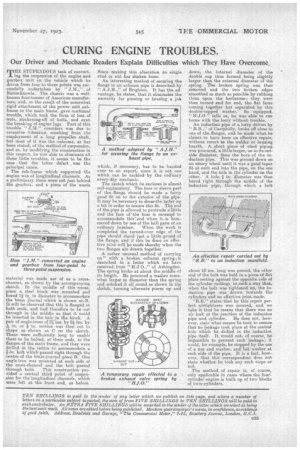
The sub-frame which supported the engine was of longitudinal channels. As a preliminary these were cut just behind. the gearbox, and a piece of the waste
material was made use of as a crosschannel, as shown by the accompanying sketch. In the middle of this ',cross-, piece a steel block was mounted and bored 1i in in diameter to accommodate the brass journal which is shown at.B. It will be observed that this is flanged at both ends, and had therefore to be cut through in the middle so that it could be inserted in the hole in tle block. A pair of angle-irons of 21-ins. by 2i ins. by 15, in. or in. section was then cut to shape as shown at C on the sketch. These were sufficiently long to enable them to be bolted, at their ends, to the flanges of the main frame, and they were drilled in the centre to accommodate a fin, bolt which passed right through the centre of the brass-journal piece B. One angle-iron was mounted at each side of the cross-channel and the bolt passed through both. This construction provided a central third point of suspension for the longitudinal channels, which were left at, the front end, as before.
Since making this alteration no single stud or nut has shaken loose.
An interesting method of securing the flange to an exhaust pipe is described by " A.J.H.," of Brighton. It has the advantage, he states, that it eliminates the necessity for pinning or brazing a jolt which, if necessary, has to be handed over to an expert, since it is not one which can be tackled by the ordinary every-day mechanic.
The sketch which he encloses is almost self-explanatory. The boss or sleeve part of the flange should be made a fairly good fit on to the exterior of the pipe. It may be necessary to dress-the latter up a bit in order to ensure this fit. The end of the pipe is allowed to protrude a little and the face of 'the boss is recessed to accommodate this end when it, is hammered down by use of the ball pane of an ordinary hammer. When the work is completed the turned-over edge of the pipe should stand just a little proud of the flange, and if this be done an -effective joint will be made thereby when the two flanges are drawn together..
A rather unusual method of carrying on" with a broken exhaust spring t.is described in a letter which we have received from " H.J.0.," of Ashingdon. The spring broke at about the middle of its length. He procured a washer somewhat larger in diameter than the spring and notched it all round as shown in the sketch, turning alternate piecee up and down, the internal diameter of the double cup thus formed .being slightly larger than the external diameter of the ,spring. The broken spring was then removed and the two broken edges smoothed as much as possible by rubbing them upon the kerbstone; they were then turned end for end, the flat fates coming together but separated by this double-cupped washer.So equipped, "H.J.0." tells us, he was able to run home with the lorry without trouble.
An induction pipe of a lorry driven by " R.B.," of Caerphilly, broke off close to one of the flanges, and he made what he claims to have been an effective repair, without resort to the welder or brazing hearth. A short piece of steel piping was procured, a little larger, as to its outside diameter, than the bore of the induction pipe. This was ground down on an emery wheel until it was a good taper fit at each end into the pipe, on the one hand, and the hole in the cylinder on the other. A hole in. -diameter was then bored right through the idclie of the induction pipe, through which a. bolt
about 18 ins, long was passed, the other end of the bolt was held in a piece of flat plate resting against the opposite side of the cylinder castings, in.such a way that, when the bolt was tightened up, the induction pipe was drawn towards the cylinders and an effective joint made. "R.B." states that by this repair perfect airtightness was secured, and we take it that he means that there was no air leak at the junction of the induction pipe and cylinder. He does not, however, state what means he toox to ensure that no leakage took place at the central . hole which he drilled in the induction pipe itself. It would not, of course, be impossible to prevent such leakage; it could, for example, be stopped by the use of a nut and washer, and felt washer at each Gide of the pipe, It is a fact, however, that this correspondent does not state whether he took any such steps or not.
The method of repair is, of. course, only applicable in cases where the four.cylinder engine is built up of two blocks of twin-cylinders.