


THE LATEST GARAGE TOOLS AND APPLIANCES.
Page 46
Page 47
Page 48
If you've noticed an error in this article please click here to report it so we can fix it.
New Devices which will Find their Way into the Better-equipped Garages and Enable Repairs to be Carried Out instead of being Sent Elsewhere.
THE TOOLS and appliances which have been shown at this year's motor trade exhibitions and intended for use in the various operations entailed in motor repairing are of a more practical kind than those we have seen hitherto. Many of such tools have, in the past, been designed by men who have obviously had no experience in repair work, and who have perhaps had no knowledge of the conditions prevailing in the ordinary garage, and they have
seldom suvived long enough to enable them to appear at the next Show. This year, however, several new departures have. been seen—devices which, we feel sure, have come to stay and will find their way into many of the better equipped garages. Apart from the tools which had been produced and were already on the market for the purpose of truing crankshafts there are two new models which are of interest.
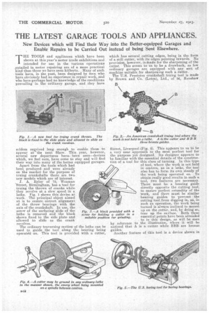
J. A. Ryley of 73, Weaman ‘`I-Sitreet, Birmingham, has a tool for , truing the throws of cranks while they revolve at a slow speed in a lathe. Fig. I shows this device at 'work. The principal object aimed at is to ensure correct alignment of the throw bearings with the axis of the crankshaft. In use, the screw of the surfacing slide of the lathe is removed and the block shown fixed to the side plate and allowed to slide as the crank revolves.
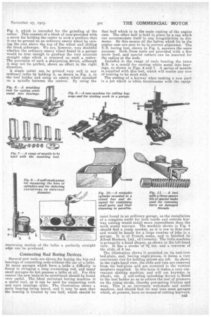
The ordinary traversing motion of the lathe can be used tp guide the tool along the bearing being operated on. This tool is provided with a cutter, which has several cutting edges, being in the form of a mill cutter, with its edges pointing inwards. No provision, however, is Made for the sharpening of the cutter. This seems to us to be a drawback, as few ordinary garages are equipped with any sort of machine suitable for sharpening such a cutter. The U.S. Precision crankshaft truing tool is made by Brown and Co. (Loton) Ltd., of 56, Renshaw
Street, Liverpool .(Fig.. 2). This appears to us to be a very near approach to the most perfect tool for the purpose. yet designed. Its designer appears to be familiar with the essential details of the construction of a tool for this class of turning. In this type of tool, where the work is not held in centres, as in a lathe, the tool also has to form its own steady of the work being operated on. To obtain really good results in such a tool, two features are necessary. There must be a bearing guide directly opposite the cutting tool-, to ensure perfect rotundity of the work, and there must be similar bearing guides to prevent the cutting tool,from digging in, as, in such an operation, the work being turned is always inclined to mount up on the cutter, and, by doing so, tear up the surface. Both these essential points have been attended to in this design, as will be seen by reference •to the illustration where it will be noticed that A is a cutter while BBB are bronze guides.
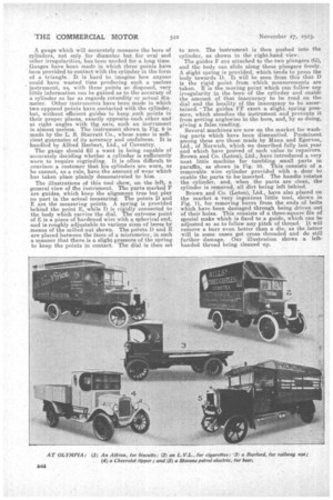
Another feature of this tool is a device shown in Fig. 3, which is intended for the grinding of the cutter. This consists of a block of iron.provided with a screw for holding the cutter in such a position that it can be ground on an ordinary emery wheel by raising the rest above the top of the wheel and sliding the block sideways. We are, however, very doubtful whether the ordinary emery wheel found in a garage would be true enough to produce the very accurate straight edge which is required on such a cutter. The provision of such a sharpening device, although it may not be perfect, shows an effort in the right , direction.
A single cutter can be ground very well in any ordinary lathe by holding it, as shown in Fig. 4, in the tool holder and using an emery wheel mpunted on a spindle between the centres. By using the
Connecting Rod Boring Devices.
Several new tools are shown for boring the big-end bearings of connecting rods without We use of a lathe. At many garages which have a lathe a difficulty is found in swinging a long connecting rod, and many' small garages do not possess a lathe at all. For this reason the new tools tia be mentioned should be found very useful. The Ideal universal boring machine is a useful tool, as it can be used for connecting rods and main bearings alike. The illustration shows a main bearing being bored, and it may be seen that the bearing is located by one half, which should be that half which is in the main casting of the engine case. The other half is held in place by a cap which can accommodate itself to any irregularities in diameter. By this means all the halves which lie in the engine case are sure to be in correct alignment. The U.S. boring tool, shown in Fig. 5, answers the same purpose. Both these tools are provided with a fine screw feed, and special cutters can be inserted for the radius at the ends.
Included in the range of tools bearing the name K.B. is a mould for casting white metal into, bearings, as shown in Figs_ 6 and 7. A series of moulds is supplied with this tool, which will enable any size of bearing to be dealt with.
The cutting of a, keyway when making a new part is a job which is -often troublesome with the equip rnent found in an ordinary garage, as the installation of a complete outfit for both inside and outside key-. way cutting would entail more expenditure than. the work would warrant. The machine -shown in Fig. 8 should find a ready market, as it is low in first cost and would be handy for a large number of jobs in a garage. It is of French make, and is handled by Alfred Herbert, Ltd., of Coventry. The little machine is primarily a hand shaper as shown in the left-hand view. It has a stroke of shapers ins, and a traverse of
the slide,of 9 ins.
The illustration shows it mounted on its cast-iron bed-plate, and, having angle:pieces, it forms a very convenient vice for holding almost any job. As shown in the right-hand view, the slide and ram are removed from the bed-plate and are mounted in the vertical members supplied. In this form it makes a, very convenient slotting machine, and will cut keyways in wheels, etc. A self-acting unlocking'device is fitted to the tool holder so as to relieve the tool of pressure on the rising stroke, thereby preventing friction and
i wear. This s an extremely well-made and useful machine, and should find its way into most garages which, at present, have no means of cutting keyways.
A gauge which will accurately measure the bore of cylinders, not only for diameter but for oval and other irregularities, has been needed for a long time. Gauges have been made in which three points have been provided to contact with the cylinder in the form of a triangle. It is hard to imagine how anyone :could have wasted time producing such a useless instrument, as, with three points so disposed, very little information can be gained as to the accuracy of a cylinder so far as regards rotundity or actual diameter. Other instruments have been made in which two opposed points have contacted with the cylinder, but, without efficient guides to keep such points in their proper places, exactly opposite each other and at right angles with tIke axis, such an instrument is almost useless. The instrument shown in Fig. 9 is made by the L. S. Starrett Co., whose name is sufficient guarantee of its accuracy and usefulness. It is handled by Alfred Herbert, Ltd., of Coventry.
The gauge should fill a want in being capable of accurately deciding whether a cylinder is sufficiently worn to require regrinding. It is often difficult to convince a customer that his cylinders are worn, as he cannot, as a rule, have the amount of wear which has taken place plainly demonstrated to him.
The illustrations of this tool show, on the left, a general view of tile instrument. The parts marked F are guides, which keep the alignment true but play no part in the actual measuring. The points D.and E are the measuring points. A spring is provided behind the point E, while D is rigidly connected to the body which carries the dial. The extreme point of E is a piece of hardened wire with a spherical end, and is roughly adjustable to various sizes of bores by means of the milled nut shown. The points D and E are placed between the faces of a micrometer, in such a manner that there is a slight pressure of the spring to keep the points in contact. The dial is then set
to zero. The instrument is then pushed into the cylinder, as shown in the right-hand view.
The guides F are attached to the two plungers (G), and the body can slide along these plungers freely. A slight spring is provided, which tends to press the body towards D. It will be seen from this that D is the rigid point from which measurements are taken. E is the moving point which can follow any irregularity in the bore of the cylinder and enable the amount of that inaccuracy to be read on the dial and the locality of the inaccuracy to be ascertained. • The guides FF exert a slight spring pressure, which steadies the instrument and prevents it from getting anglewise in the bore, and, by so doing, giving a false reading.
Several machines are now on the market for washing parts which have been dismantled. Prominent among these are those made by Mann and Egerton, Ltd., of Norwich, which we described fully last year and which have proved of such value to repairers. Brown and Co. (Loton), Ltd., have introduced a very neat little machine for tumbling small parts in paraffin, as shown in Fig. 10. This consists of a removable wire cylinder provided with a door to enable the parts to be inserted. The handle rotates the cylinder, and, when the parts are clean, the cylinder is removed, all dirt being left behind.
Brown and Co. (Loton), Ltd.' have also placed on the market a very ingenious little tool, shown in Fig. 11, for removing burrs from the ends of bolts which have been damaged through being driven out of their holes. This consists of a three-square file of special make which is fixed to a guide, which can be adjusted so as to follow any pitch of thread. It will remove a burr even better than a die, as the .latter will in some cases get cross threaded and do still further damage. Our illustration shows a lefthanded thread being cleaned up.