


B.I.C.E.R.A. Pump-injector
Page 76
If you've noticed an error in this article please click here to report it so we can fix it.
AN injection pump and nozzle combined in one unit are described in patent No. 830,963. The injector is hydraulically powered and can be worked by highly compressed 'fuel in a large engine, or, in smaller engines, the pressure of the lubricating oil may be used. The patent comes from The British Internal Combustion Engine Research Association, 111-112 Buckingham Avenue, Slough.
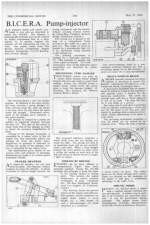
The drawing shows a unit for smaller engines. In addition to the spray nozzle, the body contains .a pump plunger (1). Fuel arriving from the inlet (2) passes a one-way valve (3) and enters the space under the plunger. Downward movement of the plunger gives injection in the usual manner.
The plunger is worked by a piston (4) subject to engine-oil pressure through the port (5). The area of the piston is many times that of the plunger in order to obtain the necessary magnification of force.
Timing' of the plunger movement is controlled by a rotary valve in the oil supply line; this alternately admits and releases oil from the piston space. Regulation of quantity is obtained by varying the stroke of the plunger; this, too, is controlled by the rotary valve.
The specification gives details of the various units and contains 13 drawings. References are made to an earlier patent numbered 746,280.
TRAILER DRAWBAR
A'improved drawbar, for use with close-coupled, four-wheeled trailers, is shown in patent No. 830,417. It allows variations in relative height between the
towing attachment and the tractor, without creating vertical forces. (B. Dixon-Bate, Fieldfare, Rowton Bridge, Christleton, Chester.)
The towing eye is placed at the apex of a triangulated frame pivoted to the trailer on a pair of pins (1). The angle of pivot is limited by a pin-and-slot link (2), 8 in. movement being allowed at the towing eye.
The pivoting movement is damped by a hydraulic dash-pot (3). This contains no springs and resists rapid movement. To avoid unnecessary wear of the dash-pot, m'nor movements are absorbed by rubber bushes (4).
PREVENTING TYRE DAMAGE TWIN-TYRED wheels can pick up 1 stones which become firmly wedged between the tyre side walls to cause local scuffing. Patent No. 829,870 covers a simple device which warns the driver when a stone has become lodged. (J. Marshall, The Orchard, St. Martins Avenue, Bawtry. Notts.)
The proposed indicator comprises a switch made from two coil springs, one inside the other. The springs are held in an insulating bush and do not normally touch each other. When a stone wedges between the tyres (shown in chain lines) it strikes the spring on each turn of the hub and closes an electric circuit to trigger a light or buzzer.
COOLING BY BOILING
ENGINES can be more efficient at temperatures higher than those normally reached. Patent No. 831,404 develops this principle to keep the water in the cooling system at boiling point. This permits the engine temperature to remain constant irrespective of load. (Tacchella Inc., 746 East Washington Boulevard, Los Angeles 21, California, U.S.A.) The drawing shows the general layout of the engine and radiators. The primary circuit comprises the engine water jacket, a steam header (1), a cold header (2) and a heat-exchanger (3) whiCh functions as a condenser.
The heat-exchanger leads to a conventional external radiator (4) with a circulating pump (5) at the bottom. A small oil cooler (6) is also incorporated.
HEAVY-VEHICLE BRAKE
ABRAKE specially designed for heavy vehicles is described in patent No. 830,429. (Automotive Products Co., Ltd., Tachbrook Road, Leamington Spa.) A sheet-metal backplate has an anchor block (1) bolted to it and, at the diametrically opposite point, a bracket for the operating mechanism. The shoes are castings and each has a thrust plug (2) in one of its ends. The plug has flats on it and slides in a groove.
The other end of each shoe is provided with an adjuster comprising a screw and nut (3); the latter is cut into gear teeth which, by meshing with a common crownwheel, enable adjustments to be made to both shoes.
The operating mechanism comprises a cam (4) which can be rocked by an external lever. When the cam is turned, 't forces rollers (5) apart. The rollers thrust on the shoes through short levers. These are pivoted on the backplate at the points 6 and give a mechanical advantage to the roller force.
SPRUNG WHEEL
PATENT No. 828,323 shows a wheel with a resilient member between the rim and the hub. A rubber ring is used this is of V-section for transverse location. It can be pre-stressed during assembly. The patent comes from Megallgummi G.m.b.H., Han noversche Strasse 88, Haraburg-Hamburg, Germany.