


A Power-assisted Braking System
Page 70
If you've noticed an error in this article please click here to report it so we can fix it.
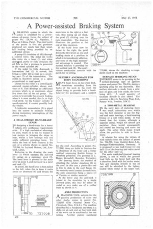
ABRAKING system in which the action is amplified by a powerdriven oil-pump, forms the subject of patent No. 728,344 (G. Piganeau, 3 Place de l'Alma, Paris). The chief point of the patent is that the pressures employed are much less than usual, full braking being provided by an additional device.
A pump (1) circulates oil idly through a control valve. The pedal (2) works this valve via a lever (3) and when depreged, partly or fully obstructs the oil flcrw so that a pressure is generated in the wheel cylinder (4).
If the pedal be fully depressed, a lost-motion link (5) is moved; this brings a roller (6) to bear On a revolving part (7) of the transmission. The roller is therefore driven at a speed proportional to road speed.
Driven-by the roller it a centrifugally operated master-cylinder, shown endways at 8. This develops an additional pressure which is, at maximum, about five times that of the oil pump. The action is to provide the greatest braking when it is most needed, that is, at high road-speed. As the booster cylinder is speed-operated, it cannot possibly lock the wheels.
A hydraulic accumulator (9) is piped into the system to maintain braking during momentary interruptions of the power supply.
A DUAL-STROKE HAND-BRAKE LEVER
IN designing a hand-brake for a heavy 1 vehicle, two conflicting requirements arise. If a high mechanical advantage be used, much of it will be wasted in lost motion in bringing the shoes to bear, whilst a low leverage will not apply sufficient operating force. To make the best of both features is the aim of a scheme shown in patent No. 725,9%, by Leyland Motors, Ltd., Leyland, Lancs.
Referring to the drawing, the main lever (I) which operates the pull-rod (2) swings on a stationary pivot (3). The hand lever is pivoted to the main lever at point 4, and moves it via a pawl and rack (5).
In action, the hand lever is first pulled to the left; when this is done it rocks about an abutment (6) and thrusts the main lever to the right at a fast rate, thus taking up all stack, the pawl (7) clicking over its rack meanwhile. The drawing illustrates the position at the end of this operation.
If the hand lever now be thrust to the right, the pawl drives the two levers as one and braking starts at a position in which it is immediately effective, and none of the high mechanical advantage is wasted. The normal hold-on is provided by the toothed rack (8). The pawlrelease mechanism controls both pawls for re-setting.
FLEXIBLE ANCHORAGE FOR BODY STANCHIONS
Tt ilANY buses have, in the lower deck, IVI stanchions extending from the backs of the seats to the roof, the object being to provide both a handhold for the passengers and a support
for thg roof. According to patent No. 727,908, these are liable to fracture due to distortion of the body and a better method, employing flexible fixings, is therefore proposed. The patentee is C. Deans, Grovehill, Beverley, Yorkshire.
The drawing shows the method of attaching the tubular. stanchion (I) to the roof; in this case a piston-like end is free to slide in the roof flange (2). No metal-to-metal contact is made here, the only connection being a sleeve (3) of Ferodo or similar material.
At the lower end, the seat-back is joined to the stanchion by a single pivoted joint; this may be either of metal or may make use of a rubber bush as shown at 4.
AXLE PRODUCTION
A MACHINE-TOOL suitable for the ri quantity production of axles and other shafts, comes in patent No. 723,885 (The Natonal Acme Co., Cleveland, Ohio, U.S.A.). The machine described has a headstock and there is a slide-rest at each end, so that both ends of the work can be machined at the one setting. Another patent, numbered SURFACE SPARKING PLUGS INTEREST seems to be growing in the I surface-discharge type of ignition system and patent No. 724,016, shows a sparking plug for use therewith. The surface electrode is made from a mixture of glass and iron oxide, the 'latter being 40%. A small quantity of titanium dioxide is also added. The patentee is K.L.G. Sparking Plugs Ltd., Putney Vale, London, S.W.15.
A TWO-METAL BEARING
IN the early days of motoring there I was much controversy over which was the best material to use for bigend and main bearings, a hard-wearing bronze or a soft white metal. It was found that the bronze, although a superior metal, would not absorb grit particles; these would consequently roll round the bearing and score the shaft. The softer white. metal would allow. the particles to sink in harmlessly.
A scheme for using the virtues of both metals forms the subject of patent No. 726,799, from Daimler-Benz A.G., Stuttgart7Unterttirkheim, Germany. It is proposed to use lead-bronze for one half (1) of the bearing and white metal for the other half (2).
The main crankshaft-journal bearing shown, is one in which the greatest load fails on the lower half and this is therefore lined with the harder metal. Any grit particles Present in the oil can still be absorbed by the lighterloaded white metal in the upper half.