


13OSCH IGNITION AND LIGHTING COMBINATION,
Page 13
If you've noticed an error in this article please click here to report it so we can fix it.
Details of a New Combined Component with Several Unusual Features.
WHEN DYNAMOS for lighting the lamps on motor vehicles were first brought into general service, certain efforts were made to combine these machines with magnetos, in order, to simplify the drive and enable the electrical part of the equipment to be treated as a unit.
At first such efforts did not prove highly successful, for the small dynamos employed at that time were not nearly so reliable as those which can be obtained to-day consequently, When failures occurred both the lighting and ignition were affected, as in most cases the whole unit had to be sent away for repair by qualified electricians. Later, however, with the increase in reliability, the question of embodying the two devices in the one casing again came to the fore, and in this connection we may refer to an interesting combined instrument of this type which has rec.ently been developed by the Robert Bosch Magneto Co., Inc., of U.S.A.
. It is marketed in three sizes, the dynamo outputs of which are 80, 100, and 130 watts respectively. The largest model develops this output at a speed of 450 r.p.m. whilst the others require a speed of 6d0 r.p.m.
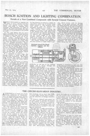
So far as the generation of electric current is concerned, the dynamo and magneto act independently, so that failure of one does not affect the operation of the other. The dynamo is shuntwound and 'has four poles, whilst its voltage is maintained approximately constash bY the use of a regulating 'resistance which is brought into and out of action by means of an electro-magnetic vibrator, the coil for which is connected across the dynamo terminals. In its general construction, the dynamo closely resembles the former instruments built by Bosch, but in the new model the hearing plate at the magneto end serves also for mounting the magneto and keeping it in correct alignment. The' magneto, however, .• differs radically from previous Bosch practice, for the armature is stationary, whilst the pole pieces, which are of annular form, rotate around it. The armature, however, carries both the primary and secondary windings,as is usual. The rotating frame carrying the magnets is mounted on the tapered end of the dynamo shaft, thus doing away with the need for separate bearings for the magneto and, consequently, reducing the overall length of the whole machine, although, to our mind, there seems to be rather more overhang than is usually considered correct design.
The contact breaker and distributor are both carried on a shaft which is per.
pendicular to the axis of the rotating Magnet and is driven through the medium of. helical gears.
Annular ball bearings of the ordinary type are employed both on the dynamo shaft and the vertical shaft, and an interesting feature ,is the automatic timing device, the advancing of the ignition being effected by means of a ball-type centrifugal ,governor, which alters the position of the vertical shaft in relation to that for the dynamo. This is achieved in a very simple manner. The helical gear is slidably mounted on the forward portion of the frame carrying the rotating magnet. One side of this . gear is formedinto a disc, whilst the halls are carried between this disc and a second
disc, which rotates with the dynamo shaft. As the speed increases, the balls are flung outwards, and pressing against the curved face of the disc on the gear force this towards the magneto, thus altering the relative positions of the helical driving gear and the driven gear,' The timing can also be controlled by hand, for which purpose the housing of the contact breaker and the distributor head are so arranged that they can be rotated to a certain maximum angle in relation to the vertical shaft, the timing range permitted being 36 degrees on the crankshaft, but where hand and automatic timing are both required the in strument is arranged so that one half of the advance is controlled by hand and the other half automatically. In order to avoid bearing friction and the possibility of sticking due to the expansion of bushes, the contact-breaker arm is supported by springs. The regulator for the voltage and the switch for cutting out the battery are located within the dynamo housing at the etoininutator end, extept in the smallest model, where they are on the top of the dynamo under a cover. Great care has been taken to protect all the current-carrying 'parts from dirt and moisture, and provision is made for the ventilation of the magneto through ori. fices in the contact breaker.