


Valve Rocker Automatically Adjusted
Page 58
If you've noticed an error in this article please click here to report it so we can fix it.
A SELF-ADJUSTING valve rocker PA. comes in patent No. 686,362, from Daimler-Benz A.G., Stuttgart-Unter
ttirk.heim, Germany. The take-up is performed by hydraulic pressure originating in the lubricating oil system of the engine.
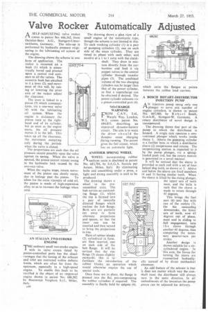
The drawing shows the scheme in one form of application. The rocker is mounted on a bush (1) which is eccentrically bored and pivoted upon a central rod common to all the valves. The eccentric bush has attached to it a lever (2), and movement of this will, by raising or lowering the pivot axis of the rocker adjust the clearance.
The lever is linked to a piston (3) which communicates, via a one-way valve (4) with the lubricating oil system. When the engine is stationary the piston rests at the righthand end of its cylinder, but as soon as the engine starts, the oil pressure moves it to the left. This takes up all the clearance, the movement occurring only during the periods when the valve is closed.
The proportions are such that the oil pressure cannot possibly open the valve against its spring. When the valve is opened, the piston cannot retreat owing to the hydraulic lock caused by the one-way valve.
When the engine stops, return movement of the piston can slowly occur, due to leakage past the piston. To allow for the extra viscosity of cold oil, the piston is made of high-expansion alloy so as to increase the leakage when cold.
683,704
■ AN ITALIAN TWO-STROKE ENGINE
THE ordinary small two-stroke engine with its valve events timed by piston-controlled ports has the disadvantages that the timing of the exhaust and inlet are restricted within definite limits, which are often far from the optimum, especially in a high-speed engine. To enable this fault to be rectified is the object. of an improved engine shown in patent No. 686,502 by Meccanica Verghera S.r.1., Milan,
The drawing shows a plan view of a small engine of the motorcycle type, though the scheme is not limited to this. To each working cylinder (1) is a pair of pumping cylinders (2), one on each side of the main cylinder. They are timed in phase with each other, and revolve at a 110 1 ratio with the crank
shaft. They draw in mixture directly front the carburetter and feed it via poppet valves to the central cylinder through transfer pipes (3). The combined volume of the two charging cylinders can be larger than that of the power cylinder, so that a supercharge can be obtained if desired. The power cylinder exhausts via a piston-controlled port (4).
NO-CHARGE WARNING
FROM C.A.V., Ltd., Warple Way, London, W.3, comes patent No. 684,855, describing an improved dynamo-battery circuit. The aim is to warn the driver sh ould the dynamo cease charging during running. The patent gives the full circuit, which has an automatic light.
ANOTHER SPRING WHEEL
A WHEEL incorporating rubber rIresilient units is disclosed in patent
No. 683,704, by S.A.G.A. Societa per Azioni, Milan, Italy. By eliminating bolts and assembling under a press, a light and strong assembly is said to be produced.
The drawing shows a wheel in the preassembled state. The hub carries an outstanding flange (1), whilst the rim is formed into a pair of inwardly directed flanges which enclose the hub flange. Both sets are partially cut away to form alternate projections and spaces, so that the inner one can be inserted and then turned to bring the projections in line. '
Pairs of rubber blocks (2), cylindrical in form. arc then inserted. one on each side of the hub flange. It will be noticed that the rim flange (3) slopes slightly outwards; this is to facilitate the introduction tubber blocks, an operation which would otherwise require the use of special tools.
Once these arc in place, the flange is pressed into the flat, pre-compressing the rubber cylinders if required. The assembly is finally held by spigots (4), of the which unite the flanges at points between the rubber load carriers.
A BOSCH ROTARY-DISTRIBUTOR INJECTION PUMP
A N injection pump using only one plunger to serve any number of engine cylinders, is Shown in 'patent No. 685,980, by R ober t Bosch, G.m.b.H., Stuttgart-W, Germany. A rotary distributor of novel design is incorporated.
The. drawing shows that part of the pump in which the distributor is housed. A single cam operates a conventional plunger Which works inside sleeye I. Above the pumping cylinder is a further bore in which a distributor sleeve (2) reciprocates and rotates. The reciprocating motion is imparted to it by the pump plunger, via a springloaded push rod, but the rotary motion is generated in a novel manner.
It will be noticed that the sleeve is provided at each end with a set of four helical dog teeth, as shown at 3. Above and below the sleeve are fixed members (4 and 5) having similar teeth. When the sleeve is lifted by the rising plunger, the upper sets of teeth meet, and the helix is such that the sleeve is made to rotate through 45 degrees.
This brings the fuel port (6) into line with one of the outlets (7).
On the . succeeding downstroke, the lower sets of teeth, now 45 degrees out of phase, meet and in sliding to full engagement, turn t h e sleeve through another 45 degrees, thus completing the necessary quarter-turn per
stroke. • Another design is shown suitable for a six.cylindered engine. In this case, the forces for turning the sleeve are transmitted hydraulically instead of by direct mechanical abutment.
, An odd feature of the scheme is that it does not matter which way the camshaft runs; the distributor will always turn in the same direction. In all embodiments of the invention the pump piston can be adjusted for delivery.