


Constant-pressure Injection System
Page 36
If you've noticed an error in this article please click here to report it so we can fix it.
A Resume of Recently Published Patent Specifications
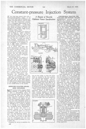
IT has long been known that with a compression-ignition engine, if the rate of fuel feed could be suitably controlled, the peak pressure need be little more than the compression pressure, with a consequent improvement in the power-to-weight ratio. A fuel injection scheme claimed to approach this ideal forms the subject of patent No. 542,844 by G. Kammer, High Austby, Middleton; Ilkley, Yorks.
Actually, the scheme is a variant of what is known as " pilot " injection, with the difference that . the fuel is injected first in a fine stream at a,very high pressure (up to 10,000 lb. per sq. in.) and then at a faster rate under q. lower pressure. Furthermore, in view of the conditions mentioned in the first paragraph, it is proposed to use a high engine compression, 22 to 1 being mentioned.
It is stated that after the initial high-pressure injection, the low-pressure charge can b,e injected at about twice the usual rate Without risk of sooting; it is in fact claimed that the total injection angle need not exceed 10 degree§ of crankshaft rotation.
The drawing shows a section of the pump plunger, which operates generally on standard principles. There are, however, two pipe-lines to each injector, one of which is led from the upper exit (1) whilst the other is connected to a species of spill-port (5). In operation, after the inlet port (2) has been covered, fuel is delivered out of port 1 until port 5 is uncovered by a helically edged groove (4). Thereafter the remaining fuel travels via this route at a faster rate.
Quantity is controlled by a second helical edge (3) co-operating with the inlet port (2) in the usual manner. The high and low pressures are adjusted by the strength of the closing springs of the needle-valves in the nozzles.
IMPROVED FLOATING BRAKE SHOE EXPANDER AANY modern brakes employ a floatMing expander to permit the shoes to have a self-centring action to correct unequal facing wear, but this— particularly in the case of slidingwedge ekpanders—sometimes leads to trouble owing to the ingress of dirt. To provide a floating member which is at the same time completely sealed, is the object of a scheme shown in patent No. 542,885 by H. J. Pratt, G. Manley and A. Girling, all of Guildhall Buildings, Navigation Street, Birmingham.
It will be seen that there is an hydraulic cylinder of the transverse type, in which the piston (1) moves a rectangular wedge (2) so as to force apart the shoe-operating tappets (3). The wedge (2), however, is not fixed to the piston, but is free to slide sideways in a rectangular slot, the outermost wall of which is formed by a slidin Plate (4y.
A spring (5) Serves to mainiain fric
tion on the wedge, so that the latter tends to remain in the best position once this has been assumed. The act of applying the brakes, however, momentarily compresses the spring and lifts the wedge away from plate 4, so allowing the wedge to move to a new position. if need be. This freeing action is permitted by giving the wedge slight top and bottom clearance in its slot.
This appears to be regarded as an important detail of the invention. What actually happens .1s that the rollers between the tappets (3) and the wedge (4) offer a resistance to the downward movement of the latter so that the plunger bears hard against it.
CONVERTIBLE TRACTOR FOR
HAULAGE AND ROTARY TILLING Q OMEWHAT involved claims are made for,,, a scheme embodied in a design of agricultural tractor described
in patent No. 542,837, bearing the name F. Porsche, Stuttgart, which gives a line on the latest German prac tice in this respect. Apparently, the main idea is to provide a dual-purpose machine, although it is called " agricultural " in the specification.
The proposal is to build a standard tractor (having a three-ratio gearbox) suitable for maximum speeds of
15 kilorrts.p,h. (9.3 in,p.h.), and to supply a rotary-tilling attachment
.incorporating a two-speed gear permitting a minimum speed of 1 kilam.p.h. (0.6 m.p.h.).
Presumably, the objects are to enable a machine tcr,, be manufac tured in large numbers, so that it can be produced at a low cost, by marketing a single basic model for both industrial and agricultural use; to avoid the need for a Man, who wishes to do only haulage, to pay the higher price of the plough and tilling tractor, and .to allow such a man, in the event of his
requirements altering, easily. to render his machine suitable for the more onerous duties.
Other advantages quoted are that the construction is simple, that when the rotary-tilling attach. ment is in position the high speed for towing is still available, and that the operation of converting does not demand skilled labour.
Whilst the patentee may have good justification for his scheme and his claims, our views, briefly, are that the inclusion of an additional ratio is not such a weighty matter as to make a very big difference in cost; that indus trial tractors are unsuitable for agriculture for other reasons besides ratio, and that nearly all farmers require to do trailer towing, as well as ploughing, so that for them a con version is unnecessary, although it may be convenient for the manufacturer. Furthermore, we regard the operation of replacing theistandard final drive by the tilling unit, in the case of this tractor, ps beyond the capability of unskilled labour. It entails withdraw ing bearings and gears and separating the bevel pinion from its crown wheel. The rotary-tilling unit (2) is secured by a flange joint at 3. In standard form, the place of cover 4 is taken by cover 5, of shaft assembly 43, by shaft assembly 7, etc. Drive to the rotary tiller is from unit 8 which, it will be nOted, is not interchangeable with the corresponding wheel (0).
All gear for raising and lowering the
rotary implement is detachable. -A
good feature is that in performing these two operations the supplementary gear reduction is automatically disengaged and engaged, respectively, through the medium of control 1, and a cross-lever, not shown, interconnecting it with the lifting apparatus.