


A SIMPLE AND INEXPENSIVE PORTABLE CRANE.
Page 30
If you've noticed an error in this article please click here to report it so we can fix it.
A Resume of Recently Published Patents.
AN INGENIOUS, simple, and inexpensive type of portable crane, which is particularly easily adaptable for a commercial motor vehicle, although not necessarily confined in its application to that use, is described in specification
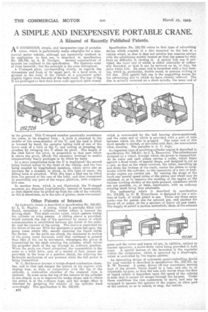
No. 192,726, by A, E. Gocidger. Several constructions of interest are outlined in the specification. We illustrate some of them herewith ; but the principle is the same throughout. A U-shaped piece, corresponding closely, as regards the dimensions and form of its upper part, to a hood stick, is pivoted to the body of the vehicle at a convenient point slightly higher than theesida of the body itself. The legs of the, U are prolonged so that their lower ends approach quite closely to the ground. This U-shaped member practically constitutes the' crane, in its simplest form. A hook is attached to the middle of the cross-member of the U, and the load is lifted or lowered by hand, the operator taking hold of one of the lower ends of a limb of the U, and raising or lowering the crossbar by swinging the Til about its pivot. The length of the limb below the pivot, in proportion to that part which is above the pivot, affords the necessary leverage to enable comparatively heavy packages to be lifted by hand.
In a more complicated form the Tj is duplicated,' the second being located nearer to the front of the vehicle, and the two being coupled by longitudinal members, which serve also as runways for a crossbar to which, in this type of crane, the lifting hook is attached. With this type a load can be lifted from the ground at the rear of the lorry, and then transposed to practically any part of the wagon platform, with comparative ease.
In another form, which is not illustrated, the U-shaped members are disposed longitudinally, instead of transversely, 3-) that objects may be picked up from the side of the vehicles, as this is sometimes, as in the case of girders, more convenient.
Other Patents of interest.
An hydraulic clutch is described in -specification NO, 192,827, by L. G. Hughes. A easing, -which is partially filled with liquid, surrounds a cylinder, within which is located the driving shaft. This shaft carries vanes, which operate within the cylinder as wing pumps. A sliding sleeve is provided, which contras the size of the apertures by means of which communication is established between the inside of the cylinder and the interior of the casing. The sleeve is controlled by the driver of the car. With the apertures or ports full open, the pump vanes rotate idly, merely churning the liquid inside the device. As the ports are closed, the resistance to motion • of the pump vanes increases, until that resistance is greater than that of the car to movement, where-upon the power i5 transmitted by the shaft rotating the cylinder, which drives the .propeller shaft of the car through an ordinary gearbox. -When the ports are closed altogether, the transmission is the same as a solid drive, and, as a matter el fact, means are provided., in the form of a positive clutch, for relieving the hydraulic mechanism of any pressure while the full power is being transmitted.
W. C. liolclerness favours a 'wedge-shaped combustion cham• her, and to that end designs the pistons of his engines with sloping tops, so that, in conjunction with the top of the cylinder, a combustion chamber of the required form is realized. In some eases the top of the interior of the cylinder is also sloped, so as to improvathe wedge shape, and in others the piston is of the ordinary type, and the wedge effect is obtained by designing the interior of the cylinder head accordingly. The specification is No. 192,841.
628 Specification Na.-192,738 refers to that type of advertising device which consists of a disc mounted on the hub of a vehicle wheel, so that it does not revolve but remains always with the advertising matter located so that the passer-by may, . have no difficulty in reading it. A special hub cap is pro' vided, the inner end of which is either internally or externally threaded, so that it can be screwed on to, or into, the main wheel huh Its outer end is furnished with a ball bearing, which is, preferably, double raced, to prevent rocking of the disc. This special hub cap is the supporting means for the advertising disc to which we have already referred. The disc is actually mounted on a short spindle, the inner end of which is surrounded by the ball bearing above-mentioned, and the enter end of which is provided with a pair of nuts between which the ,clise is gripped. The outer end of this short spindle is slotted, or provided with flats, for convenience when erecting. The patentee is A. C. Jago. An ingenious type of revolving-cylindee engine is described in specification No, 192,811, by J. L. Demartim. The cylinders are mounted on a wheel, through which the•power is transmitted. At its outer end each piston carries a roller, which bears against a fixed track, of special shape and designed to act as a cam, so that as the wheel revolves, the roller, travelling up and down the inclines of the track, causes the piston to reciprocate within the cylinder, as the operations of a two or fourstroke engine are carried out, By varying the shape of the track any special speed ratios of the piston and wheel may be obtained, so as to improve the working of the engine as the various working strokes of the cycle proceed, renditions which are not possible, or, at least, practicable, with an ordinary rotating shaft being thus attainable. The carburetter which is described in specification No. 174.058, by G. H. Tremolieres, is designed to use a mixtnre of fuels, of which petrol is one. There are three entry ports—one for petrol, one for exhaust gas, and another for heavy oil or waterer for a mixture of heavy oil and water. The supply of petrol is suction controlled; those of the exhaust
gases and the water and heavy oil are, in addition, subject to maneal operation, a screw-down valve being. provided in both• eases. _A special feature of the invention is the regulator within the carburetter, which is operated by a diaphragm, which is controlled by the engine suction,
An interesting design of automatic speed-controlling device for road vehicles is described in specification No. 192,727, by R. W. Tarrant. A pump, driven off any convenient moving part of the ehassis, forces liquid to a ram, and also to an adjustable by-pass, so that the ram only moves when the flow of liquid (which is dependent upon the speed of the vehicle) is such that it cannot all escape through the by-pass. Under those conditions the ram commences to move, and may be arranged to operate the ignition of the engine, or other part of the control, so as to retard, or stop, the vehicle.