


TIPPING GEARS.
Page 30
If you've noticed an error in this article please click here to report it so we can fix it.
A Resume of Recently Published Patents.
A tipping gear which permits the body of the lorry to be canted in any desired direction is described by T. Herdman in No. 179,466. A turntable is mounted on the chassis, and upon the turntable are double sets of rails' upper and lower. The container, as the patentee calls the lorry body, is mounted on these double rails on grooved wheels, and is -moved thereon by means of the familiar handoperated screw-and-nut gear.
The turntable is mounted on what passes for a roller bearing. A circular channel is secured to the chassis, and in the channel, mounted transversely, are a number of rollers. A suitable flat ring, secured to the under side of the turntable, runs upon these rollers, the dimensions of channel, rollers and plate being such that the last named is guided in the first.
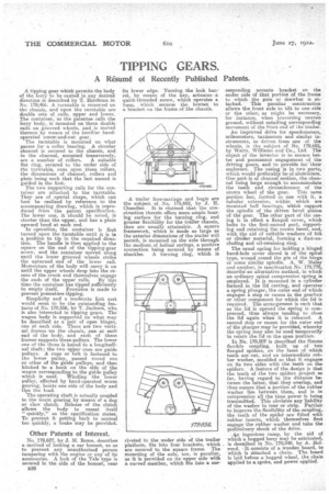
The two supporting rails for the container are attached to the turntable.
They are of special shape, which can hest be realized by reference to the accompanying drawing, -which is repro duced from the patent specification. The lower one, it should be noted, is shorter than the upper, and has a plain upward bend at each end.
In operation, the container is first turned upon the turntable until it is ha a position to tip in the required direc tion. The handle is then applied to the square on the end of the tipping-gear screw, and the container moved along until the lower grooved wheels strike the upturned end of the lower rail.
Momentum of the body will carry it on until the upper wheels drop into the recess of the crook and themselves engage the ends of the upper rails. By this time the container has tipped sufficiently to empty itself. Provision is made to prevent premature tipping.
Simplicity and a moderate first cost would seem to he the outstanding fe,a. tures of No. 179,856, by T. Jackson, who is also interested in tipping gears. The wagon body is supported on what may be described as a pair of open hinges, one at each side. There are two vertical frames on the chassis, one at each end of the body, and each of these frames supports three pulleys. The lower one of the three is keyed to a longitudi nal shaft; the two upper ones are guide pulleys. A rope or belt is fastened to the lower pulley, passed round one or other of the guide pulleys, and then hitched to a hook on the side of the wagon corresponding to the guide pulley which is used. Winding the lower pulley, effected by hand-operated worm gearing, hoists one side of the body and tips the load.
The operating shaft is actually coupled to the worm gearing by means of a dog or claw clutch. Release of the clutch allows the body to reseat itself " quickly," as the specification states. To prevent it getting back to normal too quickly, a brake may be provided.
Other Patents of Interest.
No. 179,627, by J. M. Rome, describes a method of locking a car bonnet, so as to prevent any unauthorized person tampering with the engine or any of its accessories. A lock of the Yale type is secured in the side of the bonnet, near
its lower edge. Turning the lock bar:rel, by means of the key, actuates a quick-threaded screw, which operates a lia.sp, which secures the bonnet to a bracket on the frame of the chassis.
A trailer fore-carriage and bogie are the subject of No. 179,669, by J. H. Chandler. It is claimed that the construction therein offers more ample hearing surface for the turning ring, and greater flexibility for the trailer chassis, than are usually attainable. A square framework, which is made as large as the exterior dimensions of the trailer will permit, is mounted on the axle through the medium of helical springs, a Positive connection being assured by means of shackles. A turning ring, which is riveted to the under side of the trailer platform, fits into four brackets, which are secured to the square frame. The mounting of the axle, too, is peculiar, as it is provided on its upper side with a curved member, which fits into a cor responding arcuate bracket on the under side of that portion of the frame to which the pole or drawbar is attached. This peculiar construction allows the front axle to tilt to one side or the other, as might be necessary, for instance, when traversing uneven ground, without entailing corresponding movement, of the front end of the trailer. An improved drive for speedometers, mileometers, taximeters and similar in struments, as driven from one of the wheels, is the subject of No. 179,695, by Watts, Williams and Co., Ltd. The object of the inventor is to ensure better and permanent engagement of the driving gears, and to provide for their enelosure. The casing is in two parts, which would preferably be of aluminium. One part is of channel section, the channel being large enough to accommodate the teeth and circumference of' the crown wheel of the gear. This same portion has, formed in one with it, a tubular extension, within which are mounted ball bearings, which support the spindle of the driven bevel pinion of the gear. The other part of the casing is in effect a flanged cover„ which bolts to the first-named part, supporting and retaining the crown bevel, and, with the aid of suitable washers of felt or similar material, forming a dust-excluding and oil-retaining ring.
The usual spring for holding a hinged hand-hole cover closed is of the spiral type, wound round the pin of the hinge or some similar spindle. A. W. Maley and another, in specification No. 179,778, describe an alternative method, in which an ordinary spiral compression spring is employed. It is mounted in a• cylinder formed in the lid casting, and operates a spring plunger, he outer end of which engages a stop or recess in the gearbox or other component for which the lid is required. The arrangement is such that as the lid is opened the spring is compressed, thus always tending to close the lid again when it is released. A second stop or recess for the outer end of the plunger may be provided, whereby the spring may also be used temporarily to retain the lid in the open position.
In No. 179,807 is described the Simms flexible coupling, built up of two flanged spiders, on the faces of which teeth are cut, and an intermediate rubber washer, moulded so that it engages on its two sides with the teeth on the spiders. A feature of the design is that the teeth of the two spiders project so far, having regard to the distance between the latter' that they overlap, and thus ensure that a portion of the rubber washer lies between them, and is in coinpression all the time power is being transmitted. This obviates any liability of the washer to tear or strip. Further to improve the flexibility of the coupling, the teeth of the spider are fitted with rubber inserts, which themselves first engage the rubber washer and take the preliminary shock of the drive.
An ingenious ramp, by the aid of which a bogged lorry may be extricated, is described in No. 179,349, by A. Hol. royd. -It consists of a wooden board, to which is attached a chain. The hoard is laid before a bogged wheel, the chain applied to a spoke, and power applied.