


THE SPRINGING OF COMMERCIAL VEHICLES.
Page 18
Page 19
Page 20

If you've noticed an error in this article please click here to report it so we can fix it.
The Problem of Providing for the Variation Between Laden and Unladen Weights, and a Suggested Solution.
By Engineer-Designer.
THE account of the experiments carried out by Messrs. J. I. Thornycroft and Co., Ltd., described in The Commercial Motor of April 25th (p. 291 et seq.) and the paper read by Mr. Remington before The institute of Automobile Engineers on " The Design and Functioning of Laminated Automobile Suspension Springs," bring the important matter of the springing of motor vehicles to the very forefront, and have attracted the attention of.;a, much wider field than had previously paid regard tothe subject.
The life and cost of upkeep ..of a vehicle largely depend upon the efficiency of the springs, especially those vehicles which have to operate in places where roads are rough. It has been suggested that the spring maker is
the person from whom we might expect improved methods of design and construction. This however, is not the ease in actual practice, as the spring maker has not the opportunities for testing springs under all sorts, of conditions possessed by the maker of ,the vehicle. Another reason is that the spring maker is usually bound up 'with the present form of springe—that is to say, leaf springs—and is hardly likely to experiment in other kinds of springs which might, if ,successful, divert the trade into other channels
The designer of the vehicle is the right person to look to for improvements. The springs of to-day vary, from cart springs only in detail ; the maiui features remain the same, and it is a great question whether this type of spring is the right one for commercial vehicles, either for goods or passengers. Mr. Remington gives us an enormous number of figures which do not seem to throw any very new Tight on the subject. His investigations seem to be principally in connection with pleasure cars, and, as the conditions prevailing in these cars are Bo totally different from those of commercial vehicles, his figures are not very helpful in the matter. A commercial vehicle differs from a pleasure car in the following points:— I. The vehicle runs usually on solid tyres instead of pneumatics.
2. The difference in loaded and unloaded weight is BO much greater than in pleasure cars that it sets up entirely new conditions. 3. The height from the ground of the -centre of gravity is much greater than in a pleasure ear and "roll" has more carefully to be studied; this is especially the case in top-deck buses.
4. Owing to the lower speed " rebound " is practically non-existent in the form we get it in pleasure ears.
It is as well to make perfectly clear what is the function of a spring on a. commercial vehicle, loaded and unloaded.
It is a. well-recognised fact, by those who have had experience in the upkeep of commercial vehicles, -that far more damage is done to all parts through vibration while running light than when running -with a full load. In the first place, the engine is relieved of much load, and as drivers are only human, they will try to get home as fast as possible after depositing their goods. Those who have been the sole passenger on the• back seat of an otherwise empty char-à-bancs cannot have failed to notice that the best springs of to-day, which were designed for a full load, cannot possibly accommodate themselves to the unloaded condition, no matter how skilfully proportioned.
A good deal has been said against overloading, but, from a user's point of view, this can hardly be avoided occasionally, so the springs should be like every other part of a motor vehicle, in that they should not be seriously damaged by occasional ill use. Therefore, if an occasional overload is to be allowed for (which it certainly should be), the difficulty of designing a spring to suit all conditions is increased.
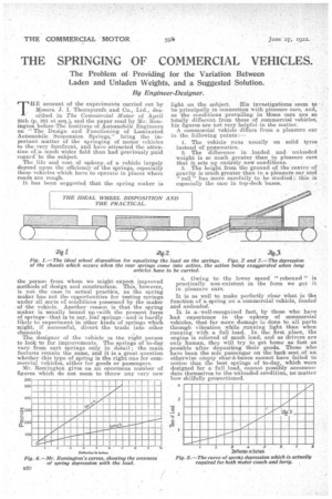
As vehicles are constructed to-day there is very little depression in the front springs when loaded, as a large proportion of the weight is behind the mar axle. Were it possible to construct a vehicle with its wheels disposed as shown in Fig. I, the conditions of front and rear springs would be identical ; but, as this is not possible for obvious reasons, we must consider front and rear springs separately. There is very little complaint of vibration arising from, the front wheels, and, so long as the position of the steering rods is designed with due regard to the angles taken by the rod from the steering arm to the front axle, matters in connection with the front springs may very well be left as they are. Fig. 2 shows -what takes place when the rear springs 'come into action. Any movement in the spring itself is exaggerated at the very rear of the • vehicle owing to the whole chassis turning itself into a lever with the front axle as its pivot.In cases where long articles—such as timber, iron girders, etc. —have to be carried, this action is much further exaggerated, as is shown in Fig. 3. In the carrying of certain classes of goods, tail-board loads have to be reckoned with.
That such loading is bad we well know, but the owner must not be kept too strictly. to what the manufacturer likes and thinks good for the vehicle. The vehicle must be useful to its owner in all circumstances.
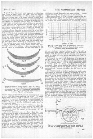
All these instances go to show that the rear springs must be able to withstand, at times, a good deal more than their normal load. If this is admitted, it -is hard to see-how the same spring, if of the usual form, can accommodate itself to the very heavy stress it may be expected to withstand, and at the same time be a suitable spring for running unloaded. Leaf springs may be said roughly to extend in an even progression with the load. That is to say, if one half-ton depresses the springs one half-inch, each further half-ton will depress it a further half-inch, until a load of four tons would produce a total depression of eight inches. These figures are only for the purpose of illustration. The curve shown in Fig 4 is one prepared by Mr. Remington and shows, the evenness of the depression with the load. That parallel helical springs extend in exactly the same manner will be seen by looking
at any ordinary spring balance., where it will be 'found that each ounce' pound, stone, or hundredweight will be marked off in exactly even progression, in spite of what some text-books may say to the contrary.
So long as the curve of deflection of a spring is as shown in Fig. 4, it is:a sign that that spring is totally unsuited for a vehicle which has;to run with a very varied load. :For a char-hebanes or Iorry, a curve, such as shown in Fig. 5, is what is required. This woald enable the vehicle, when running unloaded, to be on light springs, which will automatically become stronger as the load is increased.
An effort towards a perfect spring was made some time back by forming a spring, as shown in Fig. 13, where the leaves were separated so that the load was carried by as many leaves as it required, and no more. This did not seem to turn.out a success, as the flexing of the leaves, while acting without the support of the others, was confined to that part immediately near the palm, with the result that breakages took place there. Further efforts were made by forming the spring into a series.of groups of leaves, as shown in Fig. 7. The results, so far as easy riding went, were good, but the springs were wanting in durability. Springs with a great amount of camber will show a more suitable curve than flat ones—i.e., the shackles are arranged in an exaggerated form, as shown in Fig. 8, as the pressure required to bring the shackles to the position shown in Fig. 9 is comparatively small, and increases as the spring comes nearer to
the fiat, thus giving an inconstant progression of deflection in relation to load, which is exactly what is required of a spring, and nearer aptroaches the ideal curve in Fig. 5.
Spiral or helical springs have been tried in various forms,hut never with great success on heavy vehicles. The usual form has been a parallel helical spring which extends in an even progression, and consequently came to the end of its motion before the main
spring began to act, which would be like linking a light spring balance, which stopped at, say, .five pounds, to one that went up to a hundred. The small one would extend to its fullest extent, and then come to a stop when the large one had only got to five pounds. This would give us a curveeas shown in Fig. re, which would not be all that it required.
With supplementary springs which come to a stop at the end of their movement, there is a hammer blow which is irritating to passengers, and those which have no safety device against overload are likely to be overstrained. In spite, however, of the comparative fa,ilure, up-to now, of suPpleinentary springs to perform the correct function, it is probably to some form of supplementary spring that we may look for a solution of the problem of the perfect spring foroommereial vehicles.
Much has been said about movement of shackles increasing the wear of the joints and increasing the difficulty of lubricating them.. Efforts have been tirade to reduce the amount of movement in shackles by reducing the camber of the springs, and in the ease of Messrs. Thornyeroft they have actually designed their springs so that. they lie in a straight line. when half loaded, so that the movement of the shackles is reduced to the minimum. It is true that the movement is reduced, but it is a question whether a reduced movement is good under a heavy and continuous load.
Where there is a very heavy constant pressure for the area, as in the ease of a spring shackle, lubricant is likely to be pressed out from between the surfaces, and, unless there is sufficient movement to bring a, fresh supply of lubricantat each reversal of movement, it Is hard to see how such a joint can be kept in order. It is well recognized by those who have had to study lubrication in all its phases that a joint, where the oscillations are km than the arc of contact of the pin with its hole, will always give more trouble in the matter of lubrication than one where the movement is greater. The less the movement the more the trouble of hibrioatian, as it is utterly impossible to force lubricant between the surfaces of a shackle and its pin where the pressure per square inch is so high that nothing short of a hydraulic ram would be any good to get the lubricant where it is actually required:
It is generally admitted that no damping effect is required in a vehicle of the lorry or motor coach type, as there is no periodic rebound as with a pleasure car. This being the case, there is no reason why shackles should not be made to act as freely as possible. Pew designers "realize the effect, that a Stiff working shackle has in nullifying the. good
work of -the springs. Roller bearings, or rocker edges, similar to those used in a Morse chain, as B.2.2 suggested in The Commercial Motor a few months ago, would help the springs more than most people realize. Stiff or rusted-up shackles are responsible for much bad action of springs and are the cause of many breakages.
Some addition to the present leaf spring, which will enable it to function properly, is probably more likely to prove a solution of the spring problem than any attempt to design an entirely new form of spring, at any rate for the present. Some better, form of supplementary spring, which can easily be. attached to existing springs and which will enable a vehicle to be run unloaded without shaking itself to pieces, should find favour. It muSt, however, be simple, reliable, not liable to he strained by overloading, should not cause trouble if it went out of action, and must be adjustable to any weight of vehicle within certain limits.
A device recently patented seems fairly to fill these requirements and we shall expect to hear more of it in the near future. Fig. 11 shows .a side elevation of this supplementary spring applied to the rev end of a rear spring. The application to an existing chassis is quite easy, for the rod which crosses the chassis is lowered, as is shown in the illustration, by.rnea,ns of 'a block E, so as to allow the links of the supplementary spring room to work. The shackle is double and is pulled from its straight line by means of a spring F.. When unloaded, the spring F asserts itself and pulls the centre of the shackles to the position shown in A. As the load is increased to the normal the shackle straightens itself and extends the spring as shown in B.
When an extra 'heavy load falls on the shackle, it practically conies out of action by becoming a straight line. No matter how much overload is brought on the shackle its spring cannot be overloaded or damaged. The action of the supplerae,n
tary spring and that of the leaf spring blends one into the other without any hammer blow.screwed rod and nut provide an easy method of ad-; justing the spring to the chassis to which it is fitted.
A number of springs ca,n be used arranged as shown in Fig. 12 or more than one row can be used if necessary.
Fig. 13 shows a curve of deflection which.seems to be exactly what is required, advancing, as it does, in a very inconstant progression, until the two shackles assume practically a straight line, so that, no matter how great the overload may be, the sup, plementary spring cannot be damaged. It must ho clearly understood that the main spring can act simultaneously with the supplementary spring.