


Body Jointing Methods Reveal Future Trends
Page 40
Page 41

Page 42
If you've noticed an error in this article please click here to report it so we can fix it.
says Alfred Woolf, B.A.
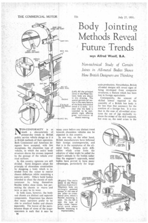
Non-technical Study of Certain Joints in All-metal Bodies Shows How British Designers are Thinking NON-CONFORMITY is as much a characteristic of, present-day trends in British public service vehicle design as it is in British methods of their operation. Both Continental and American designers have accepted, with few exceptions, the chassisless type of vehicle, in which the entire body structure shares the stresses imposed by the passage of the vehicle over road surfaces.
In this country opinions are still divided, Some designers adopt the principle of chassisless construction by designing a body which is intended from the outset to restrict chassis deflection whilst remaining a separate entity. Others build bodies intended to cheat the chassis of such assistance by being themselves flexible within close limits, but permitting the chassis to weave and twist as may be its wont.
In both cases, however, the body and chassis are distinct and separate omponents. Experience has shown that many operators prefer to be able to overhaul bodies and chassis separately. The layout of the maintenance shops of some of the larger operators is such that it may be B6 many years before any distinct trend towards chassisless vehicles can be expected in this country.
In one way, on the other hand, British manufacturers have followed their foreign contemporaries, and that is in the acceptance of the allmetal body. Despite early difficulties which arose from the adoption of what might be called the joiner's attitude to the bodies rather than the engineer's approach, metal bodies have proved to have many advantages, particularly for large scale production. Nevertheless, British all-metal designs still reveal signs of being developed from composite structures; a feature which has been lost in foreign equivalents.
Consequently, the amount of skilled labour required in the assembly of a British bus body is far less than that necessary for the erection of a foreign bus. It is true that in the case of all-welded structures the use of jigs markedly reduces the extent of the skill required, but even so, the need arises in the assembly of a foreign welded body for a large proportion of specialized operatives. In building a British body a wide variety of less highly skilled workmen is used.
The independent approach shown by bodybuilders in the United Kingdom to the problem of designing for rapid and large-scale production has necessarily resulted in a greater variety of designs than is to be found in foreign products. Detail variations rather than fundamental deviations characterize the chassisless French, Italian and German buses.
In addition, the idiosyncrasies of individual chassis makers impose another variation on body design. Quantity manufacturers therefore design bodies which are either adaptable to any shape of chassis, or which ignore any provisions for body mounting made by the chassis designer. From quite simple origins, therefore,, there develops an astonishing range of different methods of constructing bus bodies.
Discounting, for the moment, those bodybuilders whose all-metal structures are no more than composite designs with steel or light alloy in place of timber members, there are two basic differences between the types at present being produced. Some manufacturers build metal bodies employing tubularor chanbeI-section framings covered with unstressed panels. The framing is either sufficiently robust to withstand the stresses set tip by the chassis, or precautions are taken to alleviate the extent of these stresses. A body in which the framing alone bears the stresses must, if it is to last, include particularly robust members, which sometimes are not easily incorporated.
Other bodybuilders — especially those with extensive aircraft design experience—adopt a method largely native to this country, This is the stressed-skin design, in which the panels of the body are arranged to relieve the body framing of some of its load. Stressed-skin bodies, again, may be attached to the chassis in such a way as to leave the chassis some room for movement, the stressing of the panels being designed to take the loads imposed on the body by its payload of passengers.
More commonly, the stressed-skin body is intended to make a complete box-girder of the chassis-body combination, leaving the springs of the vehicle to absorb all the shocks set .tip by the passage of the wheels over the roads.
The interposition of an underframe •or body cross-bearer is another variation in the possible range of designs. Where body crossbearers are used, a chassis devoid of outriggers can be provided with a body with great ease. On the other hand, the presence of outriggers on a chassis enables some bodies to be attached directly thereto with a consequent reduction of both overall and floor height.
Typical of the underfranne type of body are the designs of Metropo ta n-Cammell-Weyman n Bodies, Ltd. This combination of two experienced constructors has carried out much research into the factors affecting the design of public service vehicles. It was found that pronounced deflections in the chassis frame caused by road shocks led to the fracture of main body crossmembers, to loose bearer-mountings and, in the case of double-deckers, to damage to thg front and rear bulkheads. A design was therefore developed, based on calculations and measurements, which relieved the body of these deflections.
Transmission of Shock Conventional bodies employ a pillar gusseted to the chassis bearers, so that all deflections occurring in the bearers are substantially transmitted to the body sides. The bulging of body sides in some older designs, and the need to replace pillars after a period of some years of operation, were signs of this interaction of body and chassis. A steel pillar, obviously, would transmit rather than absorb these bending movements, and the M.C.W. design takes this into account.
An 1-section cross-bearer only 2 ins, deep carries at its outer ends a pivoted joint which is attached to the pillar. Thus, not only is the bearer capable of bending through any imposed deflection, but the pivot joint limits the amount of angular movement to such an extent that the bearer cannot disturb the side structure.
Rather similar is the design in which the bearers consist of back-toback channel sections spaced out to provide room for a rubber mounting —a Silentbloc bush. This may be used as an alternative to the pivot joint, and both methods are employed by M.C.W. in the construction of double-deck bodies.
Rigid Beam
Other, bodies which, like M.C.W. products, incorporate structural panels constituting a rigid and continuous beam in the sides, are built on similar principles. Prefabricated bodies comprising framings manufactured by Metal Sections, Ltd., Oldbury, Birmingham, are an example.
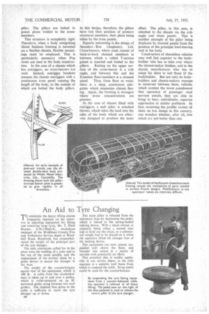
In the case of the Metal Sections design, the framing is based on an extruded light-alloy garnish rail, which constitutes the main structural member. To this are riveted interior and exterior lining panels which are connected with the seat rail. Either solid or hollow rivets are used, according to the type of chassis. To the seat rail is attached the truss panel. This is riveted to the solebar, to the back of which is bolted an angle-section welded to the main pillar. The pillars are bolted to gusset plates welded to the crossmembei s This structure is completely rigid. Therefore, when a body comprising Metal Sections framing is mounted on a flexible chassis, flexible mount,ings must be employed. This is particularly necessary when Pop rivets are used in the body construction. In the case of a chassis which has outriggers, no cross-bearers are used. Instead, outrigger brackets connect the chassis outriggers with a continuous truss panel running the length of the body, to the outside of which are bolted the body pillars. In this design, therefore, the pillars have lost their position of primary structural members, their place being taken by the truss panels.
Equally interesting is the design of Saunders Roe (Anglesey), Ltd. Cross-bearers, where used, consist of back-to-back channel members in between which a rolled T-section gusset is inserted and bolted to the
pillars. Resting on the upper surface of the cross-bearer is a crib angle, and between this and the Z-section floor-members is a stressed panel. Thus, from floor to waist, there is a deep, continuous sidegirder which minimizes chassis flexing. Again, the framing is strongest where stress concentrations are greatest.
In the case of chassis fitted with outriggers, a stub pillar is attached thereto, which takes the load into the sides of the body which are otherwise designed to produce the same
effect. The pillar, in this case,, is attached to the chassis via the crib. angle and stress panels. This is another example of the pillar being displaced by stressed panels from the position of the principal load-bearing unit in the body.
Constructors of chassisless vehicles may well feel superior to the bodybuilder who has to take over where. the chassis-maker finishes, and to the chassis manufacturer who has to adapt his ideas to suit those of the bodybuilder. But not only do bodybuilders and chassis-makers manage to construct between them, vehicles which combat the worst punishment that operation of passenger road services entails, they are able to bring to bear, individually, separate approaches to similar problems. In fact, reviewing the prolific variety of ideas on bus design in this country, one wonders whether, after all, two minds are not better than one.