


MAKING BEST USE OF THE FORD.
Page 15
If you've noticed an error in this article please click here to report it so we can fix it.
Valuable Advice on Every Phase of Ford Transport which will appeal to the Owner, Driver and Repairer.
425.—Removing and -Replacing • New Type Bands.
• The bands of the latest model can be removed through the inspection door
• of the transmission case instead of it being necessary to remove the latter entirely. Each band has a detachable ear with slotted holes in which shouldered pins (two on the gear iffind and three on the brake band) engage. They are retained by the end of the band, which has a certain amount of spring, and engage a slight shoulder on the under side of the ear at the forked end. There is alSb a hole about .1§-6. in. .,square dt that end of the band to which the detachable ear is fitted, and part of this hole protrudes slightly through a small slot at the foot of the ear.
Having removed all external fittings, the adjusting sleeve and nuts should be. slacked off or entirely removed, and the blade of a screwdriver inserted into the slot at the foot of the ear, the blade, -which should be about f-in. wide, entering the hole in the band. The band can then be levered sideways against the ear, and a click will announce that the shouldered pins have slipped forward into the slots, when the ear can be lifted off and moved from the transmission
case. The band can then be drawn out through the inspection door.
Before replacing the ear, procure a piece of old gramophone -spring about
in. in width and 3 ft. long. Soften One cud of this and cut off sufficient at each side to reduce the width to about
-pc in. Bend this end over to form a hook, which should turn inwards. Harden and temper the hooked end. Now slip the spring around the transmission drum, hook the end in the slot in the band, which will then slip back into place again by gently pushing the band and pulling the spring.
tilless such a device be employed. considerable time and trouble will almost certainly be spent in trying to refit the band, as its contour is altered in removal and return, and the end will almost always foul projections on the engine tray and sides of the transmission cover, as the clearance is but small. In some cases, although the bands have been removed through the inspection door, it has been found necessary to dismantle the transmission case in order to return them. Incidentally, an old Ford magnet will also cbme in handy for holding the nuts, of the control pedal shafts in position when refitting.
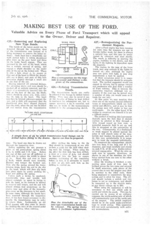
426.—Reining Transmission Bands.
The traesmission bands can easily be relined if the linings be drilled before. fitting. Time may also be Saved if one or two lengths of lining .be kept drilled in readiness for subsequent use, but to ensure accuracy a jig is essential, and this can be made to the measurements indicated in the accompanying sketch.
After drilling the holes in the jig they should be countersunk at one side to form a guide for the drill when dealing with the linings. When using the jig, after the first hole has been drilled, a rivet or a piece of a-in. rod should be inserted into the hole to ensure accurate registering of the remaining holes; in fact. it is advisable to insert a rivet or pin into each hole as the drilling is carried on.
427.—Remagnetizing the Permanent Magnets.
After a Ford engine has been running for some time the magnets are apt to become rather weak, for there is always a natural loss, and this may be accentuated by vibration and road shocks.
The result is difficulty in starting the engine, inability to run slowly, and dim lights if the lighting be dependent upon the magneto.
The engine, in the case of the 1-ton truck, may stop entirely if the lights be
turned on ; also, although the engine may run quite well light, it may stop immediately a load be applied.
If these symptoms occur it is essential that the magnets should be strength ened. The method suggested would not appeal to drivers, but to garage owners and mechanics who deal with a number of Ford vehicles. This is because the apparatus required, although not expensive if the cost can be spread over a number of jobs, Yet would seem so if made for one only.
At this point we may mention that there are on the market several different types of remagnetizers -which are both useful and effective, and it may be that the garage man will prefer to buy one ready-made. On the other hand, if he Wishes to construct one himself it is not a difficult matter.
The method of making this instrument depends upon the fact that if electric current be allowed to flow through a wire wound round an iron core, a
powerful magnetic field is set up, and this is strongest at the extremities of the core. Consequently, if a discharged or weak magnet be placed against the poles it will absorb some of the mag netism and weaken its strength, and to do this very satisfactorily it is necessary to treat the magnets individually. To construct the remagnetizer, obtain two iron bars, 8 ins, long and of I. in.
diameter, and wind carefully and evenly on each 6 lb. of 22 s.w.g. double-cottoncovered copper, wire. Wind the wire an each core in opposite directions, as shown in one of the sketches, the wire being carried from one core to the other without a break.
• After the winding is finished, a connecting piece made of iron may be bridged across the two cares and secured by small setscrews; pole, pieces of the correct size to suit the magnet may then be screwed to the other ends, these being employed to concentrate the magnetism and to allow for wear. The circuit should include a switch and two lamps to act as resistances, and should be connected up to the electric main, at any direct voltage up to 250.
When using the apparatus it will be nece4sary to find out which pole is north and which the south. This can be carried out by means of an ordinary 'compass, the north-seeking pole of which will automatically turn to the north pole of the magnet. Tfte switch employed should be of the quick make-and-break type to avoid arcing. This apparatus will not work satisfactorily with ordinary accumulators.