


Two-fuel Carburetters and Fittings. XI.
Page 4
If you've noticed an error in this article please click here to report it so we can fix it.
The Thornycroft Vaporizer—Known in America as well as in this Country for Its Efficiency.
It is perhaps only fitting with a name so widely known as Thornycroft that, in our description and comments on the Thornycroft twofuel carburetter, we should be able to refer to American opinions of it. These opinions were expressed in the course of a Paper entitled "Kerosene versus Gasoline," read by Chailes E. Lucke before the Society of Automobile Engineers in the course of the last month. (We hope to refer in detail to this Paper on some later occasion). The drawing on this page is also reproduced from the same Paper," and although' its illustrates 'well the arrangement and details of the Thornycroft fitting, it should also be reworked that this vaporizer is being developed very keenly, by J. I. Thornycroft and Co., Ltd., Caxton liouse,'Westrninster, S:W., but for reasons connected with%the patent laws, the company does not wish us to disclose at present the nature of several valuable improVements recently effected. We can, however, assure those of our readers, and there are more than a few, who are owners of Thornycroft vehicles that the latest fitting should appeal to. them very strongly on grounds both of economical and efficient working. It appears to be capable•of being fitted cheaply.
Description of the Pitting.
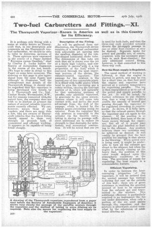
As will be gathered from our illustration, the Thornycroft device consists, of a, two-float carburetter with adjustable jet opening into the smallest diameter of the venturi-shaped horizontal choke tube. The dimensions of this tube are such that air-is drawn over the jet at a fairly high velocity, and consequently it carries'awith it a big proportion of the fuel,' which is conveyed through the next important portion; of the device, the exhaust-heated vaporizer. The passage for the mixture is . the ceptralione of two concentric pipes. It is fitted' with baffle plates which tend to give the traversing gas a rotary motion, causing the heaviest portion of it, which will naturally be that containing portions of paraffin, only partially vaporized, to gravitate to the outer circumference where it will come into contact with, and derive the most advantage from, the *all of the passage, which is heated by the exhaustgases, circulating round its exterior. From the vaporizer this rich mixture is 'conveyed to the cylinder via the throttle valve, taking in during its passage sufficient additional air to reduce its strength to that desirable for satisfactory and economical combustion. It will be noted that one jet
is used for both fuels, and that the three-way cock provided actually diverts the jet-supply passage to one or other float charriner as may be desired. Separate tanks for petrol and paraffin are, of course, required, with the' necessary pipelines to each float-chamber ; the only additional control fitting, however, is that connected to this three-way cock.
How the Heat-supply is Regulated.
The usual method of working is followed, in that the engine is started on petrol, and may be run for a short time on that fuel until the engine and vaporizer have arrived at a suitable temperature for vaporizing paraffin. The tap is then manipulated so as to cut off the petrol and supply 'paraffin to the jet. It will be noted, by further reference to our illustration, that a wing valve is fitted enable the amount of heated gas passing through the vaporizer to be regulated according to requirements. As shown, it is fully open, so that the exhaust passes through the vaporizer and out again to the
silencer. If the position is as shown dotted, then none of the exhaust passes through the vaporizer, but all of it would pass through the pipe labelled as leading to the silencer. Any position between these two extremes may be achieved as desired. It will readily be grasped that the best position for starting is that shown in the drawing. When petrol only is being used, it might be preferable, to turn all the exhaust gas direct to the silencer, but when the engine is actually running on the heavy fuel, the position of this valve would depend upon the atmospheric conditions at the time. The provision of means for regulating the heat supply is a commendable feature.
Efficient Vaporizing.
In order to increase the heatconveying properties of the vaporizer, it will be noticed that the central passage has vertical radiating fins cast on the outside of this wall ; these are of great assistance in enabling the greatest amount of heat to be extracted from the exhaust gas and transmitted to the mixture. This additional efficiency is particularly required in an instrument like the one under discussion, when enly a portion of the air used passes through the vaporizer, and the mixture is afterwards cooled somewhat by the adrniSsion of additional diluting air.