


The Soames Gear.
Page 13
If you've noticed an error in this article please click here to report it so we can fix it.
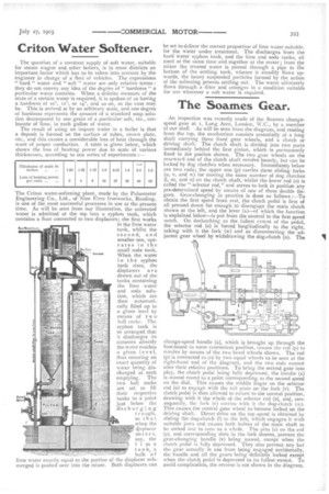
An inspection was recently made of the Soames changespeed gear at r, Long Acre, London, W.C., by a member of our staff. As will be seen from the diagram, and reading from the top, the mechanism consists essentially of a long shaft carrying three fixed gear wheels, and a clutch or driving shaft. The clutch shaft is divided into two parts immediately behind the first pinion, which is permanently fixed in the positon shown. The two gear wheels on the rearward end, of the clutch shaft revolve loosely, but can be locked by dog clutches when necessary. Immediately below are two rods; the upper one (p) carries three sliding forks (u, v, and w) for moving the same number of dog clutches (1, in, and n) on the clutch shaft, whilst the lower rod (o) is called the "selector rod," and serves to lock in position any pre-determined speed by means of one of three double fingers. Gear-changing in practice is done as follows :—To obtain the first speed from rest, the clutch pedal is first of all pressed down far enough to disengage the main clutch shown at the left, and the lever (x)—of which the function is explained below—is put from the neutral to the first speed notch. On declutching to the fullest extent of the pedal, the selector rod (o) is forced longitudinally to the right, taking with it the fork (w) and so disconnecting the adjacent gear wheel by withdrawing the dog-clutch (n). The change-speed handle (a), which is brought up through the foot-board to some convenient position, causes the rod (p) to revolve by means of the two bevel wheels shown. The rod (p) is connected to 10) by two equal wheels to be seen at the right-hand end of the diagram, and the two rods cannot alter their relative positions. To bring the second gear into play, the clutch pedal being fully depressed, the handle (x) is moved round to a point corresponding to the second speed on the dial. This causes the middle finger on the selector rod (o) to engage with the tail piece on the fork (v). The clutch pedal is then allowed to return to the normal position, drawing with it the whole of the selector rod (o), and, consequently, the fork (v) carries with it the dog-clutch (in). This causes the central gear wheel to become locked on the driving shaft. Direct drive on the top speed is obtained by sliding the dog-clutch (I) to the left, which engages it with suitable jaws and causes both halves of the main shaft to be united and to turn as a whole. The pins (z) on the rod (p), and corresponding slots in the fork sleeves, prevent the gear-changing handle (x) being moved, except when the clutch pedal is fully depressed. They also prevent any but the gear actually in use from being engaged accidentally, the handle and all the gears being definitely locked except when the clutch pedal is depressed to its fullest extent. To avoid complication, the reverse is not shown in the diagram,