The hydraulic system
Page 41

If you've noticed an error in this article please click here to report it so we can fix it.
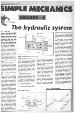
HE GIRLING master ylinder, illustrated in Figre 1, is an aluminium alloy 3sting, the cylinder portion I which is very accurately iachined to size and then ighly polished. A port at the Dttom of the reservoir perits fluid to flow from the iservoir into the cylinder. The cylinder contains a unger with two rubber seals, a ring and spring thimble and a live stem. On the reservoir end the valve stem is a valve seal id in the first 1 / 32 inch unger movement, on brake iplication, this seal closes the id port to the reservoir. Fluid in now only escape via the port the top front end of the This port is connected to the ake line and the fluid forced rough the brake line operates e brake shoes. When the akes are released, the valve icovers the reservoir port, lowing fluid to flow from linder to reservoir and vice rsa.
One type of wheel cylinder, :;luding a means of operating e handbrake, is shown in Fige 2. This cylinder is not firmly ated on the back plate, but is )e to slide in a slot cut in the ickplate. One end of the linder is closed and slotted on e outside to locate the moving d of the trailing shoe.
The cylinder contains a pis1, a rubber cup, a plastic cup reader and a small spring. A /cited lever is fitted so that its orter end fits between the two Ives of the piston. The long d of the lever protrudes rough the backplate and a ober boot is fitted around it.
It is to the end of this part of a lever that the handbrake ble is fitted. A brake adjuster fitted at the other end of the ton. The end of the leading oe sits on this adjuster.
When the brake pedal is plied, the fluid pressure forces the piston to move outwards and force the leading shoe into contact with the drum. At the moment the leading shoe makes contact with the drum the reaction force causes the cylinder to move back in its slot, so applying the trailing shoe. The available force is thus divided equally between the two shoes.
When the handbrake lever is applied, the lever forces the piston outer half to move out and apply the leading shoe. As the leading shoe makes contact with the drum, a similar reaction takes place as that described for the hydraulic application.
Any serious leak in a hydraulic brake system causes com plete failure of the footbrake system. The handbrake remains operative, but is often not powerful enough to provide an emergency stop.
As a leak may develop suddenly and without any warning to the driver, even in a well maintained system, it is not surprising that modern vehicles are fitted with systems which eliminate, at least to some extent, this particular hazard.
To provide the degree of safety necessary two master cylinders, each independent of the other, are needed. Sometimes these are physically separate, their pistons being operated through a balance beam, which normally equalizes the forces applied to them by the application of the footbrake pedal.
The motion of the balance beam is limited, so that if one system fails the other earl still be applied, although the pedal travel is increased.
The more common method is to use a tandem master cylinder, where two pistons are contained in the same cylinder. The pistons are so arranged that if one system fails the other one remains operative; separate reservoirs are provided for each piston.
The division of the brakes between the two systems always used to be such that one system operated the rear brakes while the other worked the front. In recent times some manufacturers have split the system diagonally, ie near side front and off side rear and off side front and near side rear.
In hydraulic brake systems the handbrake is mechanically operated. Figure 3 illustrates a linkage commonly used on rod or cable operated systems to I provide automatic compensation for the brakes. The force applied by the handbrake to rod -Ais equally divided between rods "Band


