


Heavy Machinery Transporter
Page 68
If you've noticed an error in this article please click here to report it so we can fix it.
D A TENT No. 856,592 deals with heavy' duty trailers such as those used for transporting machinery and the like. It shows improved mechanism for handling the load on and off the ground. (W. Martin, 816 North East Street, Kewanee, Illinois, U.S.A.)
The upper drawing shows the trailer, with its tractor (1), in the travelling position. To bring the platform to the loading position on the ground, the tractor moves forward, at the same time the front section (2) is lowered to the VACUUM-OPERATED TRAILER BRAKES
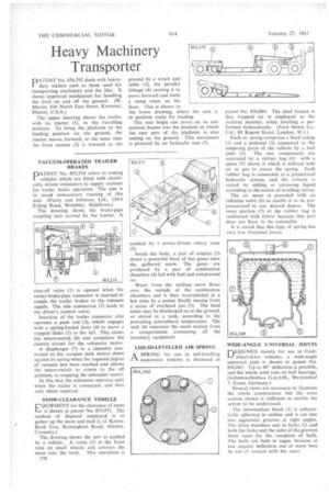
D AT ENT No. 855,574 refers to towing vehicles which are fitted with electrically driven exhausters to supply vacuum for trailer brake operation. The aim is to avoid unnecessary running of this unit. (Feeny and Johnson, Ltd., 134-6 Ealing Road, Wembley, Middlesex.) The drawing shows the brake-pipe coupling unit carried by the tractor. A
shut-off valve (1) is opened when the trailer-brake-pipe connector is inserted to couple the trailer brakes to the vacuum supply. The side connection (2) leads to the driver's control valve.
Insertion of the trailer connector also operates a push rod (3), which engages with a spring-loaded lever (4) to move a stepped slider (5) to the left. This closes the micro-switch (6) and completes the electric circuit for the exhauster motor.
• A diaphragm (7) in a chamber connected to the vacuum tank moves down' against its spring when the required degree of vacuum hasbeen reached and allows the micro-switch to return to the off position, so stopping the exhauster motor.
In this way the exhauster operates only when the trailer is connected, and then only when required.
SNOW-CLEARANCE VEHICLE
QUIPIVIENT for the clearance of snow I—, is shown in patent No. 855,971. The method of disposal employed is to gather up the snow and melt it. (J. Kenny, Birch Tree, Birmingham Road, Allesley. Coventry.)
The drawing shows the unit as pushed by a .vehicle. A ramp (1) at the front runs on small wheels and conveys the snow into the body. This operation is (736
ground by a winch and able (3), the parallel linkage (4) causing it to move forward and form a ramp when on the floor. This is shown in
the lower drawing, where the unit is in position ready for loading.
The rear bogie can pivot on its suspension beams into the position in which the rear part of the platform is also resting on the ground. This movement is powered by an hydraulic ram (5).
assisted by a power-driven rotary vane (2).
Inside the body, a pair of nozzles (3) direct a powerful blast of hot gases onto the gathered snow. The gases are produced by a pair of combustion chambers (4) fed with fuel and compressed air.
Water from the melting snow flows over the outside of the combustion chambers and is then re-circulated in a hot state by a pump, finally issuing from a series of overhead jets (5). The final water may be discharged on to the ground, or stored in a tank, according to the prevailing atmospheric temperature. The wall (6) separates the snow section from a compartment containing all the necessary equipment.
LIQUID-LEVELLED AIR SPRING
A SPRING for use in self-levelling in• suspension systems is disclosed it
patent No. 856,089. The chief feature is that trapped air is employed as the resilient member, while levelling is performed hydraulically. (Ford Motor Co., Ltd., 88 Regent Street, London, W.1.) Each air spring comprises a fixed casing ( I) and a pedestal (2) connected to the unsprung parts of the vehicle by a ball joint (3). The two components are separated by a rubber bag (4) with a space (5) above it which is inflated with air or gas to create the spring. Each rubber bag is connected to a pressurized hydraulic system, and the volume is varied by adding or removing liquid according to the action of levelling valves.
The air space is provided with an inflation valve (6) to enable it to be prepressurized to any desired degree. The inner portion (7) of the rubber bag is reinforced with fabric because this part does not have to be extensible.
It is stated that this type of spring has very low frictional losses.
WIDE-ANGLE UNIVERSAL JOINTS
DESIGNED mainly for use in frontwheel-drive vehicles, a wide-angle universal joint is shown in patent No. 856,063. Up to 40° deflection is possible, and the whole joint runs on ball bearings.
(Gelenkwellenbau Westendhof 7, Essen, Germany.) Several views are necessary to illustrate the whole construction, but the cross section shown is sufficient to enable the action to be understood.
The intermediate block (1) is substantially spherical in outline and is cut into two segmental grooves at right angles. The drive members end in forks (2) and both the forks and the sides of the grooves form races for the 'reception of balls. The balls are .held in 'cages, because at low angular deflection one or more may be out of contact with the races.