


A Swash-plate Engine Design
Page 40
If you've noticed an error in this article please click here to report it so we can fix it.
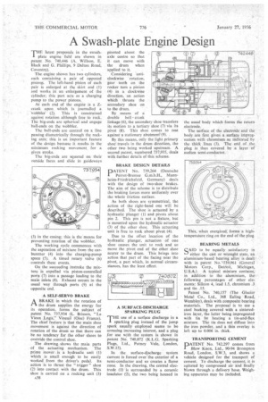
TIM latest proposals in the awash"plate engine field are shown in patent No. 740,446 (A. Willson, E. Black and G. Phillips, 9 Dalton Road, Coventry).
The engine shown has two cylinders, each containing a pair of opposed pistons. The left-hand piston of each pair is enlarged at the skirt end (1) and works in an enlargement of the cylinder; this part acts as a charging pump to the power pistons.
At each end of the engine is a Zcrank upon . which is journalled a ‘Wobbler. (2). This is constrained against rotation although free to rock. The big-ends are spherical and engage ball-ends on the wobbler.
The ball-ends are centred on a line passing diametrically through the rocking axis; this is an important feature of the design because it results. in the minimum rocking movement for a given stroke.
The big-ends are squared on their outside faces and slide in guideways (3) in the casing; this is the means for preventing rotation of the wobbler.
The working cycle commences with the aspiration of mixture from the carburetter (4). into the charging-pump space (5). A timed rotary valve (6) controls these events.
On the succeeding instroke the mixture is expelled via piston-controlled ports (7) into a passage leading to the main inlets (8). Exhaust occurs in the usual way through ports (9) at the opposite end.
A SELF-SERVO BRAKE
A BRAKE in which the rotation of the drum supplies the energy for its operation, forms the subject of patent No. 737,934 (L. Brisson, "Le Vieux .Logis.,". Vineuil (Oise) France). The chief feature is that the main shoe movement is against the direction of rotation of the drum so that there can be no tendency for the other shoes to override the control shoe.
The drawing shows the main parts .of the actuating mechanism. The prime mover is a hydraulic unit (1) which is small enough to be easily worked from the driver's pedal. Its action is to thrust the "trigger shoe (2) into contact with the drum. This shoe is carried on a rocking unit (3) A38
pivoted about the axle centre so that it can move with the drum when applied to it.
Considering 'anticlockwise rotation, gear teeth on the rocker turn a pinion (4) in a clockwise direction, an action which thrusts the secondary shoe on to the drum.
By means of a double bell crank linkage (6), the secondary shoe transfers its motion to a tertiary shoe (7) via its pivot (8). This shoe comes to rest against-a stationary abutment`(9).
By this means, only the light primary shoe travels in the drum direction, the other two being worked upstream. A second patent, numbered 737,935, deals with further details of this scheme.
BRAKE DESIGN DETAILS DIPIATENT No:. 739,264 (Deutsche 1 Perrot-Bremse G.m.b.H., Mannheim-Friedrichsfeld, Germany) deals with the design of two-shoe brakes. The aim of the scheme is to distribute the braking forces more uniformly over the whole friction surface.
As both shoes are symmetrical, the action of the right-hand one will be described. The shoe is actuated by a hydraulic plunger (1) and pivots about pin 2. This pin is not a fixture, but is mounted upon the hydraulic actuator (3) of the other shoe. This actuating unit is free to rock about pivot (4).
Due to the offset location of the hydraulic plunger, actuation of one shoe causes the unit to rock and so move the pivot end of the other shoe nearer to the drum. This brings into action that part of the facing near the pivot, a part which, in normal circumstances, has the least effect.
A SURFACE-DISCHARGE SPARKING PLUG HE use of a surface discharge in a I sparking plug instead of the jump spark usually employed seems to be arousing increasing interest, and a plug for use with the system is shown in patent No. 740,872 (K.L.G. Sparking Plugs, Ltd., Putney Vale, London, S.W.15).
In the surface-discharge system current is forced over the exterior of a semi-conductor and so creates a flame zone. In the drawing, the central electrode (I) is surrounded by a ceramic insulator (2), the two being housed in the usual body which forms the return electrode.
The surface of the electrode and the body are first given a surface impregnation with chromium as indicated by the thick lines (3). The end of the plug is then covered by a layer of molten semi-conductor.
This, when energized, forms a hightemperature ring on the end of the plug.
BEARING METALS
SA1D to be equally satisfactory in either the cast or wrought state, an aluminium-based bearing alloy is dealt with in patent No. \739,961 (General Motors Corp., Detroit, Michigan, U.S.A.). A typical mixture contains,• in addition to the aluminium, the following percentages of other elements: Silicon 4, lead 1.5, chromium .3 and tin .15.
Patent No. 740,157 (The Glacier Metal Co., Ltd., 368 Ealing Road, Wembley), deals with composite bearing materials. The proposal is to use a steel backing covered with a sinterediron layer, the latter being impregnated with tin by heating a tin-and-flux mixture. The tin does not diffuse into the iron powder, and a thin overlay is left up to 0.006 in. thick.
TRANSPORTING CEMENT
PATENT No. 742,297 comes from Blaw Knox, Ltd., 90-94 Brampton Road, London, S.W.3, and shows a vehicle designed for the transport of cement. To discharge the cement, it is agitated by compressed air and finally blown through a delivery hose. Weighing apparatus may be included.