


A Baico-extended Four-tonner
Page 55
If you've noticed an error in this article please click here to report it so we can fix it.
WE have in the past referred to the Baico system of converting fourwheeled chassis into rigid-frame sixwheelers, but recently certain improvements have been effected, these being well displayed in a four-tonner which has been introduced incorporating the well-known Willys-Manchester
chassis.
It is the first time that Baico Patents, Ltd., Baieo Place, 327a, Chiswick High Road, London, W.4, has made use of this particular chassis, and a slight . difficulty arose due to the overall frame width and the outward-facing channels that are employed for longitudinal members. This has been satisfactorily overcome by using, for the frame extension, a pair of inward-facing channels, these being placed back-to-back against the existing main members, and strengthened at the overlap by top and bottom plates. The frame members are shortened by 14 ins, and the extensions are bolted to them, the overlap being
2 ft. 6 ins. long. As the extended frame measures 6 ft. 2 ins, from the end of the shortened main frame, the length is actually increased by 5 ft. The extension members are 51 ins, deep and
3 ins, in flange width. Two extra cross-members are employed.
The familiar Baico suspension system, fully described in our issue dated September 10th, 1929, is embodied, particularly stout shackle members, in the form of steel castings, being employed because of the extra load. • The principle of the suspension is one embodying an inclined balancer arm, connect
ing adjacent ends of the semi-elliptic springs on each side of the chassis. In the case of the Willys-Manchester twotonner this balancer arm is 14 ins, long between pin centres, the fulcrum being centrally located. The rearmost shackle in this case is 101 ins, long between pin centres.
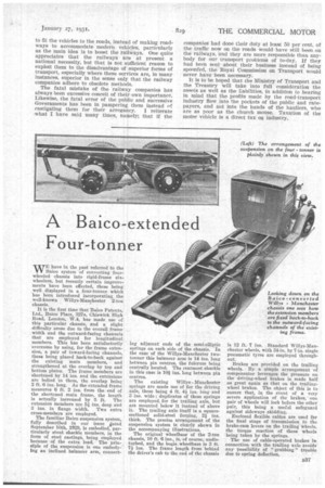
The existing Willys Manchester springs are made use of for the driving axle, these being 4 ft. 4, ins. long and 3 ins. wide ; duplicates of these springs are employed, for the trailing axle, but are mounted below it instead of above it. The trailing axle itself is a squaresectioned solid-steel forging, 21 ins. thick. The precise arrangement of the suspension system is clearly shown in the accompanying illustrations.
The original wheelbase of the 2-ton chassis, 10 ft '6 ins., is,-of course, undisturbed, and the bogie.wheelbase is 3 ft. 7-} ins. The frame length from behind the driver's cab to the end of the chassis
is 12 ft. -7 ins. Standard Willys-Manchester wheels, with 34-in. by 7-in, single pneumatic tyres are employed throughout.
Brakes are provided on the trailing wheels.. By a simple arrangement of compensator leverages the pressure on the driving-wheel brakes is made half as great again as that on the trailingwheel brakes. The object of this is to ensure that, in the event of a very severe application of the brakes, one pair of wheels will lock before the other pair, this being a useful safeguard against sideways skidding.
Enclosed flexible cables are used for the final stage of transmission_ to the brake-cam levers on the trailing wheels, the torque reaction of these wheels being taken by the springs.
The use of cable-op6rated brakes in connection with the trailing axle avoids any possibility of " grabbing " trouble due to spring deflection.