


A Résumé of Recently Published Patent Specifications
Page 54
If you've noticed an error in this article please click here to report it so we can fix it.
A Bus Body With Tubular Cross-members
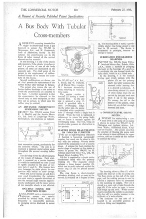
A RESILIENT mounting intended for singleor double-deck buses is put forward in patent No. 593,745 by Weymanns, Ltd., and W. Doelsworth, both of Addlestone, Surrey In this scheme, the cross-bearers are in the form of tubes instead of the normal channel-section material.
In the drawing, 1 is one of the chassis side members, 2 the tubular cross-bearer and 3 a portion of one of the body pillars; all these are duplicated on the opposite side. The chief point of the patent is the employment of rubberbushed clamps (4) to mount the cross tube on the chassis. • ' Several modifications are shown, one of v hie' permits the replacement of the rubber bushes after damage by fatigue.
The patent also covers the use of further rubber bushings at the points at which the cross-bearers are attached to the body, A further suggestion is that the cross-bearers be clamped to the chassis only at their mid-point, so that they act as springs, in which case the rubber may be omitted.
AN ADVANCED INDEPENDENT SUSPENSION SYSTEM DATENT No. 593,814 comes from J. Haefeli and the Austin Motor Co., Ltd., both of Longbridge Works, Birmingham, and discloses an indepen dent suspension system, particularly for the steerable wheels. The aim is to maintain a constant castor-action angle throughout the normal working deflection.
The drawing shows the chief features of the system, of linkages. Each stubaxle is mounted on a carrier Member (1) which is constrained by arms (2 and 3) rigidly attached to the ends of torsion bars (4 and 5). The torsion barsmay, however, be plain pivots, in conjunction with helical or other springs.
When the carrier moves up and down over road irregularities, the swinging arm ends move in opposite directions, so that the vertical angle remains approximately-unchanged, and the castor action of the steerable wheels is not affected.
ONE-BOLT FIXING FOR INJKTION PUMPS
AuXILIARIES such as magnetos and injection pumps are usually attached by several bolts, which are frequently in inaccessible positions. A clamping device disclosed in patent
A36 No. 593,052 by C.A.V., Ltd., F. Evans and W. Nicholls, all of Warple Way, London, W.3, increases accessibility ' when removing or replacing these units.
• The engine carries a brackee (1) having a semi
circular base. To the one side is screwed a strip (2) which is provided with a short overhanging ledge. On the other side, the pump is provided with a projecting boss (3) through which a single bolt iS passed. When the bolt is tightened, it endeavours to rotate the pump body, and so forces it securely against the overhanging ledge. The bolt, being on the clear side,' presents no obstruction to thespanner.
STARTER RINGS HEAT-TREATED BY INDUCED CURRENTS THE use of high-frequency induction heating is becoming increasingly popular, but much can be done in this way with the ordinary 50-cycle mains supply if the component be of a suitable shape. A scheme for heat-treating the starter rings of engines by this means is shown in patent No. 594,032, ' by H. Johnson and Ford Motor Co., Ltd., 88, Regent Street, London, W.1.
AU that is required is a. simple mains transformer fitted with the primary winding (1). The magnetic circuit includes a loose keeper member (2), which can be easily removed so that the starter ring (3) can be placed around the core.
The ring forms a short-circuited seeondary winding, and as soon as the current is switched on it begins to heat up. The heating effect is rapid, a goodsvehicle starter ring being raised to red heat in 20 seconds. The 'device is economical in principle, because no energy is wasted LUBRICATION FOR GEARBOX BEARINGS
PATENT No. 593,596, from WillysOverland Motors Inc., Toledo, Ohio, U.S.A., shows a method of pumping lubricant to the bearings of a gearbox, in particular the one housed inside the input shaft, which is in a blind hole.
In the drawing, I is the layshaft driving gear which meshes with the pinion (2) on the primary shaft: the latter contains the recessed roller bearing that it is desired to lubricate. A close-fitting shroud (3), made of sheet metal, traps the oil carried by the gear teeth and leads it up to the pinion. To convey the oil to the interior of 'the .pinion, small holes (4) are drilled through between the teeth.
A CONSTANT-LEVEL OILING SYSTEM
ASCHEME for maintaining a constant level in the sump of an engine is shown in patent No. 593,417 by V. Pilkington and Leyland Morals, Ltd., Ham Works, Richmond Road, Kingston-on-Thames. The patent describes the practice of floating the pump inlet so as always to draw oil from the upper surface, and use is made' of this feature to control the level.
The drawing shows a ficiat (I) which .carries the inlet (2) to the oil pump (3). The float pivots on the end of the inlet pipe, and the rocking motion is used to operate a separate valve (4) connected to the incoming oil supply. New oil is stored in a tank and arrives through the pipe (5); if the valve be open, it enters and brings up the level. When, correct level is reached, the supply is automatically shut off, in a similar manner to the ball-cock of .a water cistern.
The container for the new oil is located in an accessible position to facilitate filling and inspection.