


A GUIDE TO FORDSON RACTOR MAINTENANCE
Page 26
Page 27
Page 28
Page 29
If you've noticed an error in this article please click here to report it so we can fix it.
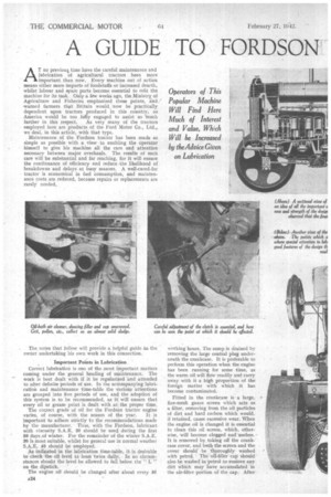
Operators of This Popular Machine Will Find Here Much of Interest and Value, Which Will be Increased by the Advice Given on Lubrication
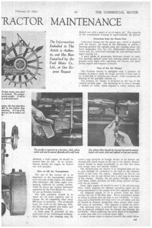
The Information Embodied in This Article is Authentic, and Has Been Supplied by the Ford Motor Co., Ltd., at Our Ex
press Request
AT no previou time have the careful maintenance and lubrication of agricultural tractors been more important than now. Every machine out of action means either more imports of foodstuffs or increased dearth, whilst labour and spare parts become essential to refit the machine for its task. Only a few weeks ago, the Ministry, of Agriculture and Fisheries emphasized these points, and warned farmers that Britain would now be practically dependent upon tractors produced in this country, as America would be too fully engaged to assist us 'much
further in this respect. As very many of the tractors ' employed here arc products of the Ford Motor Co., Ltd., we deal, in this article, with that type.
Maintenance of the Fordson tractor has been made as simple as possible with a view to enabling the operator himself to give his machine all the care and attention necessary between major overhauls. The results of such care will be substantial and far reaching, for it Will ensure the continuance of efficiency and reduce .the likelihood of breakdowns and delays at busy seasons. A well-cared-for tractor is economical in fuel consumption, and maintenance costs are reduced, because repairs or replacements are rarely needed.
The notes that follow will provide a helpful guide tia the owner undertaking his own work in this connection.
Important Points in Lubrication
Correct lubrication is one of the most important matters coming under the general hea.ding of maintenance. The work is best dealt with if it be regularized and attended to after definite Periods of use. In the accompanying lubrication and maintenance time-table the various attentions are grouped into five periods of use, and the adoption of this system is to be recommended, as it will ensure that every oil or grease point is dealt with at the proper time.
The cor,rect grade of oil for the Fordson tractor engine varies, of course, with the season of the year. It is important to adhere strictly to the recommendations made by the manufacturer. Thus, with the Fordson, lubricant with viscosity S.A.E. 20 should he used during the first 50 days ,of winter. For the remainder of the winter S.A.E. 30 is most suitable, whilst for general use in normal weather S.A.E. 40 should be employed.
As indicated in the lubrication time-table, it is desirable to check the oil level at least twice daily,. In no circumstances should the level be allowed to fall below the" L
on the dipstick. '
The engine oil should be changed after about every 56 A24 working hours. The sump is drained by 'removing the large central plug underneath the crankcase. It is preferable to perform this operation when the engine has been running for some time, as the warm oil will flOw readily and carry away with it a high proportion of the foreign matter with which it has become contaminated.
Fitted in the crankcase is a large, fine-mesh gauze screen which acts as a filter, removing from the oil particles of dirt and hard carbon, which would, if retained, cause excessive wear. When the engine oil is changed it is essential to clean this oil screen, which, otherwise, 'will 'become clog.ged and useless. It is removed by taking off the crankcase cover, and bath the screen and the cover should be thoroughly washed with petrol. The oil-filler cap should also he washed in-petrol to 'remove any dirt which may have accumulated in the air-filter portion ofthe cap. After
cleaning, a little engine oil should be poured into the felt. In no circumstances should the engine be flushed out with paraffin.
How to Oil the Transmission The use of the correct oil is as important in the transmission system as in the case of the engine, for unsuitable lubricants will cause rapid overheating, followed by serious trouble. Table II shows the various lubricants approved by the Ford Motor Co., Ltd:, for use on Fordson tractors.
The only attention needed is to check the oil level regularly and to change the oil completely after every 200 hours of operation. The oil should reach the level of the filler-cap hole, the filler being located just below and to the side of the gear leVer, A drain, plug is provided in the under-side of the transmission housing. After draining, the housing may be flushed out with a quart or so of engine oil. The capacity of the transmission housing is approximately 3i gallons.
Attentions from the Grease Gun
Lubricator fittings for the grease gun, which is supplied with the tractor, are fixed at the following 19 points:— Steering spindles (2); spindle arms (2); steering joints (2);front suspension (1); fan (1); front-wheel bearings (2); clutch arm (1); rear-wheel bearings (2) and steering-column upper bearing (1).
A good grade of grease-gun lubricant should be used. The spindles, spindle arms and steering pdints should be greased every night after operating the tractor, but other points require less-frequent attention.
Care of the Air Cleaner
The Fordson tractor is equipped with a primary air. -.cleaner, to remove chaff, the larger particles of dust and so on, it also has an oil-bath-type cleaner, which completes the filtering of the partially cleaned air.
, The primary air cleaner is mounted at the' top of the vertical air-inlet pipe. The incoming air is drawn through a number of vanes, which imparts a rotary motion and cauSes large particles of foreign matter to be thrown out through four small scoops at the top of the cleaner. Examination should be made periodically to see that the vanes and scoops have not become choked.
The oil-bath-type air cleaner is so designed that air has to pass through oil contained in the base of the chamber before it can' enter the engine. Impurities in the air are deposited in the oil and thence into a dirt trap in the •base of the cleaner. Finally, the air passes through a copperwool filter, which prevents oil from being carried througl with the air stream.
Clean, light engine oil should be used in the oil-bath-type filter, which depends for efficient operation upon the oil being maintained at the proper level and regularly changed.
An adequate supply of oil is present when the level reaches the top of the filler pipe. Every precaution should be taken to ensure that the pipe is not overfilled. A 'drain plug and a detachable dirt-trap cover are provided, and the oil -should be drained (preferably .when warm) after every 250 hours of operation. The capacity is about six pints.
The dirt-trap cover is screwed, into the base, and when this is removed sediment may be cleaned out through the hand-hole. When replacing the cover plate it is important to make sure that it is screwed down tight.
A small release valve is situated beneath the outlet elbow
of the cleaner to allow the escape of any surplus fuel or oil, and this should be inspected occasionally to ensure that it is continuing to function satisfactorily and opens and doses freely.
Other Maintenance Points
The magneto should be oiled very sparingly after every 50 hours of use, Only twoor three dfops of light oil being applied. The Wico-type magneto, Where fitted, requires lubrication at-intervals of about 200 hours. An orifice for this purpose is provided towards the rear of the magneto ,body and is indicated by a plate. Remove the screwed plug and insert light oil until the orifice is filled.
Extreme-pressure lubricant must be used in the steering box. The oil level should be examined after ,every 200 hours of running, and, if necessary, fresh lubricant added to the level of the filler plug.
The radiator should be drained and flushed out at about the same intervals. It is, of course, necessary frequently to check the waterlevel and top up with fresh water as required.
. All exposed running gear should be cleaned and checked every week to see that bolts and connections are secure, and working parts should be lubricated freely, using an oil can_ If there be any sign of oil leaking past felt washers and (lust caps, they should be replaced and any looseness in the steering joints and frontor rear-wheel bearings should be taken up.
Looseness of the steering arm may be corrected by disconnecting the halves of the ball sockets surrounding the steering-arm ball, and filing their surfaces until they fit snugly. A badly worn ball should be replaced. If the yoke pins in the steering spindle arms be loose the steel bushings should be replaced by new ones. Loose spindle pins can also be remedied by replacing the bushings in the frontwheel spindle, or, if there be excessive movement in a vertical direction,, by renewing the two spindle thrust washers.
An, adjusting nut is provided for the adjustment of the wheel bearings. After removing the hub cap, correct adjustment is obtained by screwing home the adjustment nut and then loosening it to the extent of from one-third to twothirds of a turn, allowing the wheel to rotate freely with no end play. The adjusting nut must be locked in position with a cotter pin. When carrying out this adjustment, the nut should never be forced so tight that the wheel binds, as this will immediately damage the bearing,
Running -Adjustments Which Promote Efficiency Correct adjustment of the paraffin vaporizer is necessary
for even running and full power with econoiny. Thevaporizer should be adjusted when the engine is thoroughly warm. With the governor control rod set to keep the engine running at a good speed, weaken, the mixture by screwing down the needle valve until the engine starts to run unevenly, and then gradually enrich the mixture by
opening the needle valve until the engine runs evenly and no smoke comes from the exhaust. The best setting of the needle control is soon found by actual experience. In cold weather it may be helpful to open the fuel needle about a quarter-turn more until the engine is warmed up. • As carbon tends to accumulate on the vaporizer plate, causing ,difficult starting and uneven running, the plate should be cleaned occasionally with a wire brush. It may be taken off for this purpose by disconnecting the fuel feed pipe and removing the four manifold-cover studs. Should the jet become choked with dirt or ivater, causing difficult starting or uneven running, it may be cleared by running the engine fairly fast, opening the vaporizer needle valve and quickly pulling out and returning the chdke control. The high suction thus created will usually clear the obstruction.
To ensure easy starting and full power, the plugs and contact-brehker points should be cleaned and adjusted when necessary. The correct gap setting for the sparking-plug points is .030-.033 in. Where the Bosch-type magneto is fitted, the gap between the contact-breaker points should be adjusted to .015 in. The correct gap settings for the Lucastype and Wico-type magnetos are .012 in. and .015 in.
respectively. *
If misfiring occurs, although the ignition sytem is in order, the trouble may be due to a valve not seating properly. The clearance between the valve stem and the push rod should be between .020 in. and .024 in. If the clearance be .less than .020 in., the stem of the valve may be ground to give the correct gap, care being used to ensure that the end is absolutely square. If the clearance be more than .024 in., either the valve or the rod, or both, should be replaced. Alternatively, the seat may be ground in.
Some of the common causes of difficult starting and irregular running, in_ addition to those already mentioned, deserve attention. One is choking of the vaporizer sediment bulb. This should be drained frequently by unscrewing the square-headed drain plug at the bottom of the bulb. In cold weather, water that has, accumulated in the sediment bulb my freeze. In this case a cloth, saturated in hot water, should.be wrapped around it for several minutes until the ice melts and the water may be drained out. * A punctured, float, or the fuel regulator valve in the vaporizer being stuck open, will cause flooding and too rich a mixture.
To cure air leaks at cylinder head, ,manifold or sparkingplug gaskets, make sure that the gaskets are in good condition and that the retaining nuts are tight.
Possible troubles when the machine is operating under severe weather conditions areoil or water in the magneto or on the high-tension leads, Looking After the Governor A centrifugal governor, controlled from the dash, regulates engine speed. If it be necessary to adjust the control rods, the short lever on the throttle-control assembly should be turned to its uppermost position, and the throttlecontrol arm (the longer one on the governor housing) should also be moved upwards to the same position. The block on the lower end of the rod connecting this arm to the throttle-control assembly should then be adjusted so that it is necessary to pull down the rod 1-64 in. in order to insert it in the hole in the arm and thus connect the control to the inner side of the control arm. This is necessary to prevent the load from the governor spring being transferred to the throttle stop on the vaporizer. The adjustment is correct when a piece of paper may be slipped between the stop lever and its stud. .
Compensating for Clutch Wear.
Normal wear on the clutch-release plate should be compensated for periodically by adjusting the clutch pedal. This is necessary when the clutch pedal strikes the foot plate before the clutch is fully disengaged or the brake properly applied.
' To make the adjustment, remove the cotter pin and clevis pin and screw out the rod of the clutch-release arm to the extent required, replacing the clevis pin and cotter pin afterwards.
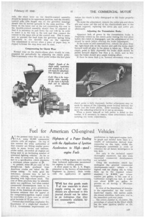
Adjusting the Transmission Brake Apparent lack of power in the transmission brake is frequently caused by the clutch pedal fouling the foot plate before the clutch is disengaged, and the adjustment"of this should be made before altering the brake adjustment. If the brake be still' unsatisfactory, remove the plate from the right-hand side of the tractor and pull the brake shaft forward until all play in the plates is taken up. When the clutch pedal is fully depressed the brake shaft should be pulled forward slightly less than in, more, and in this case the brake should give ample braking effort.
If there be more than in. forward movement when the clutch pedal is fully depressed, further adjustment may be made by means of the adjusting screw located between the clutch and the brake plates. After loosening the locknut, move the adjusting setscrew in or out as necessary.
When a power take-off or belt pulley is fittedto • the tractor, it is necessary to remove these attachments before carrying out brake adjustments.