


By R. T. Nicholson (Author of "The Book of the Ford ").
Page 23
If you've noticed an error in this article please click here to report it so we can fix it.
ACORRESPONDENT has recently asked me for a complete wiring diagram of the Ford electrical system. But such a complete wiring diagram would simply give him a headache. The way to master the complicated plan in to unravel it, and to take each circuit separately. That is precisely what I propose to do.
531 (contd.).—The Magneto Ignition Circuit.
The magneto circuit wires are red. The main magneto wire leaves the magneto terminal and passes to the terminal block or board.
That terminal block or board bothers a good many drivers. It has no electrical value whatsoever. It is simply a means of anchoring wires, sometimes of dividing a particular wire into two. You will get a better idea of any circuit by ignoring the terminal board and considering the wiresas running on continuously without a break there. From the terminal board a red wire passes to the switch. When switch key is set at " Mag." position, electrical connection is established there with the red wire passing to the coil box. There is a "bus bar" . running under all the coil units ; that is, a strip of metal which is in contact with four metal discs—one under each unit—so that the current can pass into each unit. It does so pass into each unit in turn. To simplify explanation, however, let. us suppose that the Ford is a one-cylinder engine, and that there is only one eoil unit, and only one wire leading from the coil unit to the timer (instead of four). The magneto current passes through the coil unit, out by its wire, to its terminal on the timer. The outside terminal passes into a metal strip or segment inside the timer cover, and inside that cover is a metal roller on an arm, which arm turns round continuously, being con
nected up with the engine, so that every time the roller touches the metal strip current passes from strip to roller, " earthing " through the roller and arm, and so getting back to the magneto through the frame.
True, there are four coil units, four wires running to the timer, four strips inside the timer cover. But all that this means is that the current passes through the four strips, wires, coil units, in turn, and so serves four cylinders in turn.
Inducing the High-tension Current.
Inside each coil unit are two separate coils or spirals of wire. (It is because of these spirals that a coil is called a coil.) One is the low-tension coil through which the magneto current directly passes on its way to the timer. Beside each • low-tension coil-(or wire spiral) is a much longer and finer wire coil. This is the high-tension coil proper. I donot propose to try to explain exactly what happens, and how it happens, but whenever low-tension current
passes through the low-tension coil, high-tension current is " induced" in the high-tension coil, and whenever the low-tension circuit is broken (by the trembling of the vibrators) there is momentarily such a rush of high-tension current that it jumps the gap at the plug points. The high-tension current follows this path—by one Of the lower four binding posts on dash, through a sparking plug cable, to each plug in turn, passing down the central rod of that plug, jumping the gap, and getting back to the high-tension coil by the engine metal, and through the four timer wires, which lead it back to the low-tension coil. From that low-tension coil there is a short bridge of wire that completes the high-tension circuit.
The function of the trembler action of each unit is simply to break the low-tension circuit repeatedly, the result being a series of corresponding breaks in the high-tension system, and so a series of" snappy" sparks at the plugs.
In the low-tension coil (or spiral) there are 122 turns of wire. In the high-tension coil (or spiral) there are 16,400 turns of much finer wire. The relative length and thickness of the wire in the two coils is responsible for the enormous voltage of the high-tension current as compared with that of the low-tension current. (High-tension differs from low-tension only in degree, not in kind.) The voltage of the lowtension current varies with engine speed, from almost nil to about 24. The voltage of the high-tension current varies with engine speed from almost nil to 20,000. The amperage of the high-tension current is, however, so slight that, notwithstanding the discomfort of a shock from a plug, you still survive to read why it did not Eli you!.
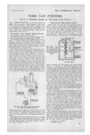
The accompanying illustration (Fig. 352) shows the four paths of lowand high-tension current. Next week we will deal with troubles that may arise In them. Meantime, assuming that your magneto is in good order, think out for yourself the various points at which the systems may break down for either of ' the two main masons I have given you :—