


Patents Completed.
Page 28
If you've noticed an error in this article please click here to report it so we can fix it.
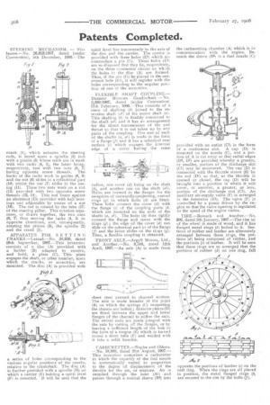
STEERING MECHANISM. — Niclausse.—No. 26,623/1907, dated (under Convention), 5th December, 1906.—The crank (1), which actuates the steering rods, is keyed upon a spindle (2) fast with a pinion (3) whose teeth are in mesh with two racks (4, 5), the latter being, respectively, fast with two nuts (6, 7) having opposite screw threads. The backs of the racks work in guides (8, 9) and the nut (6) slides in a cylindrical part (10) whilst the not (7) slides in the casing (11). These two nuts work on a rod (12) provided with two opposite screw threads (13, 14). This rod bears against an abutment (15) provided with ball bearings and adjustable by means of a nut (16). The rod is rotated by the tube (17) of the steering pillar. This rotation separates, or draws together, the two nuts (6, 7) thus moving the racks (4, 5) in opposite directions, and, consequently, rotating the pinion (3), the spindle (2) and the crank (1).
APPARATUS FOR SETTING CRANKS.—Larrad.—No. 20,929, dated 20th September, 1907.—This invention consists of a disc (A) provided with a holder (B) adapted to receive, and hold, a plate (C). This plate engages the shaft, or other member, upon which the cranks, or eccentrics, are mounted. The disc (A) is provided with a series of holes corresponding to the various angular positions of the cranks, relative to the crankshaft. The disc (A) is further provided with a spindle (D) on which a carrier (E) holding a spirit level (F) is mounted. It will be seen that the spirit level lies transversely to the axis of the disc and the carrier. The carrier is provided with three holes (El) which accommodate a pin (G). These holes (El) are so disposed that they lie, respectively, on the three concentric circles on wh:ch the holes in the disc (A) are formed. Thus, if the pin (G) be placed in the outermost hole (E1), it will register with the holes corresponding to the angular postion of one of the eccentrics.
FLEXIBLE SHAFT COUPLING.— Daimler Motoren Gesellsc.haft. —No. 2,360/1907, dated (under Convention) 17th February, 1906.—This consists of a piece of shafting (b) joined to the extension shaft (al) of the motor shaft (a). This shafting (b) is flexibly connected to the shaft (al.) and it has an arrangement for the direct transmission of the end thrust so that it is not taken up by any parts of the coupling. One end of each of the shafts (a, al) is made in the form of a flange (f) and it has a spherical rear surface (c) which engages the internal edge of a cover having the same radius, one cover (d) being on the shaft (II), and another one on the shaft (al). Holes are formed in the flanges for the reception of outwardly-projecting, curved rings () in which bolts (fr) are fitted. These bolts connect the cover (d) with the flange (i) of the coupling parts (fri which are mounted on the ends of the shafts (a, al). The bolts (h) thus rigidly connect the flange and cover with the rings (g) ; the edge of the cover (d) can slide on the spherical part (c) of the flange (f) and the latter slides on the rings (g). Thus, a flexible coupling is obtained.
FRONT AXLE.—.Argyll Motors, Ltd., and Another.—No. 8,516, dated 12th April, 1907.—An axle (A) is made from sheet steel pressed to channel section. The axle is made broader at the point (B) on which the springs (C) supporting the chassis are bolted ; distance pieces (D) are fitted between the upper and lower flanges of the channel to stiffen the axle. The swivel ends are made integral with the axle bycutting off the flanges, or by leaving a sufficient length of the web in the form of a tongue (E) which is turned round a short tube (F) and welded with it into a solid knuckle.
CARBURETTER.—Napier and Others. —No. 18,880, dated 21st August, 1907.— This invention comprises a carburetter in which the capacity of the fuel nozzle is automatically varied in proportion to the degree of displacement of the throttle for the air, or mixture. Air is supplied through the inlet (Al) and passes through a conical sleeve (BS) into the carburetting chamber (A) which is in communication with the engine. Beneath the sleeve Bs) is a fuel nozzle (C)
provided with an outlet (Cl) in the form of a continuous slot. A cap (D) is mounted on the nozzle (C), and a portion of it is cut away so that radial edges (Ds, DT) are provided whereby a greater, or smaller, portion of the discharge slot (Cl) may be uncovered. The cap (D) is connected with the throttle sleeve (B) by the rod (D1) so that, as the throttle is opened or closed, the cap (D) will be brought into a position in which it will cover, or uncover, a greater, or less, portion of the discharge slot (Cl). An auxiliary air-supply valve (F) is arranged in the extension (ES). The valve (F) is controlled by a pump driven by the engine so that the valve opening is regulated as the speed of the engine varies.
TIRE.—Bowack and Another.—No. 306, dated 5th January, 1907.—The rim (a) of the wheel is made of wood, and it has flanged metal rings (b) bolted to it, Sections of rubber and leather are alternately arranged between these rings, the portions (d) being composed of rubber, and the portions (e) of leather. It will be seen that these rings are so arranged that the portions of rubber (d) on one ring, fall opposite the portions of leather (e) on the next ring. When the rings are all placed in position, the metal flanged rings are secured to the rim by the bolts (f).