


Commercial vehicle transmissions what next?
Page 26
Page 27
Page 28
If you've noticed an error in this article please click here to report it so we can fix it.
by J. K. Todd executive, mechanical engineering group, National Research Development Corporation
IN THE past 20 years the size, weight and engine power of commercial and public service vehicles have increased greatly and transmissions have grown more complicated and more sophisticated to match increased engine power and torque, while still maintaining a high degree of reliability. Nowadays five-speed gearboxes with a splitter gear or a two-speed axle are commonplace, giving the driver the somewhat bewildering choice of 10 different gear ratios. In America five-speed boxes with three-speed axles are sometimes used, providing 15 forward gears.
It is not surprising, therefore, that since a heavy-vehicle driver may have to exert a clutch pedal force of 601b, semi-automatic, twopedal-control gearboxes are beginning to become more popular. They have been used on buses for many years now, where they have proved their reliability, which is an important point. On the goods vehicle they have one other very important advantage: the driver can change gear at full throttle, since they normally comprise an epicyclic gear train behind a fluid coupling. With a conventional spur gearbox there must inevitably be a reduction in vehicle speed during an upward change while climbing a hill which is getting less steep, and very often by the time the higher gear is engaged the vehicle speed has dropped so much that the driver needs to change down again. With a "hot shift" transmission there is no reduction in torque flow to the wheels during the change, and the higher gear can therefore be engaged and maintained with the result that hills can be climbed faster.
The obvious next step in the development is to make these transmissions fully automatic, as has already been done on public service vehicles. Automatic transmissions of American origin are already available for commercial vehicles but these use a torque converter instead of a fluid flywheel. The torque converter can multiply the engine torque, whereas the fluid flywheel is simply a coupling with no torque multiplication. Converters can reduce the number of gear ratios required but they are not normally so efficient as fluid couplings which can be locked mechanically at as low as 850 engine r.p.m. and are therefore almost 100 per cent efficient at engine speeds above this. The torque converter automatics are essentially scaled-up versions of automatic transmissions for private cars which are well known to be less efficient than their manual counterparts. Comparisons of cars with manual and automatic transmissions almost invariably show that the automatic, which in many cases is more pleasant to drive, uses more fuel and has a slightly reduced performance.
Assuming that automatic transmissions of both these types become more prevalent over the next few years, as they almost certainly must, it is interesting to consider what the next generation of transmissions after that may look like.
Future transmissions
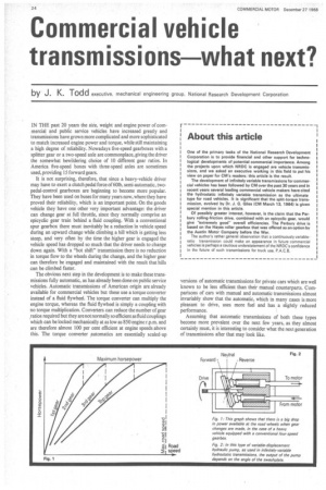
Existing gearboxes, both spur gear and epicyclic, use a number of discrete ratios and in each of these there is a fixed relationship between engine speed and road wheel speed. Horsepower against road speed in each gear ratio can be plotted as shown in figure I for a four-speed gearbox. This shows that if a change is made from one gear to the next, because of the reduced engine speed in the higher gear, there is a big drop in the power available to the road wheels. If extra gear ratios were available between each of the gears shown, the drop in power on each change would be about halved. The more ratios that are available, the smaller the drops in power on each change. If there are an infinite number of gear ratios available, maximum horsepower can be maintained at the wheels at all times, and it is likely that continuously-variable gearboxes which provide this facility will be the gearboxes of the future. Although they are continuously variable, this must be between limits, otherwise at low ratios the torque would tend towards infinity at constant horsepower.
Further advantage can be taken if a continuously variable transmission is available; the engine can be made to run at its best specific fuel consumption for any throttle setting. Since an infinite variety of gear ratios is available, an automatic control system can be designed to ensure that for a fixed throttle setting the engine will run at this optimum condition, irrespective of the load, by putting the gearbox in the precise ratio to give this engine speed with the particular road speed at that time. If a driver selected full throttle, for example, on the level road, the vehicle would settle down to run at a fixed road speed. If the vehicle then started to climb a hill, the gear ratio would automatically change down to allow the engine to continue to run at its fixed speed. Conversely, if the vehicle started to descend a hill the gear ratio would gradually change up to the highest ratio available, while still maintaining constant engine speed.
Ultimately, a continuously variable transmission could allow the use of an engine designed to run at one speed only. An engine which did not have to run over a range of speeds could probably be designed to have a better fuel consumption than conventional engines and might well be much quieter. This would be a long way in the future and for any new transmission to be acceptable it will have to be suitable for use with existing engines. Potentially, a continuously variable transmission would also be ideal for a gas turbine engine.
The ideal continuously variable transmission
A new transmission must have a number of characteristics for it to be generally acceptable; these are discussed below and some potential contenders are compared with the ideal to see how nearly they approach it. The transmission must have an adequate ratio range from the lowest crawler gear to an overdrive top gear, so that there is no need for a two-speed axle, and it must have a neutral and reverse. It must be an efficient unit so that fuel consumption is comparable with that obtained in vehicles equipped with conventional spur gearboxes and the overhaul life must be at least as good. It must not cost appreciably more than the equivalent 10-speed semi-automatic gearbox. These are probably the most important features, but there are a number of other characteristics which would ideally be desirable.
Apart from the neutral ratio which will allow the vehicle to come to rest without stalling the engine, an additional "positive" neutral must be provided, over-riding the normal control so that the engine can be revved up during maintenance without any tendency for the vehicle to move. Additionally the driver must be able to override the automatic control to select low ratios at will for descending steep hills and possibly also for ma.noeuvring. Engine overspeed protection will have to be automatic for the "hold low" condition.
Hydrostatic transmissions
A hydrostatic transmission is a hydraulic transmission basically consisting of a. positive-displacement pump and motor. Unlike a torque converter (a hydrokinetic transmission) which uses the velocity energy of the fluid, a hydrostatic transmission uses the pressure energy of the fluid to do the work.
The pump supplies high-pressure fluid to the hydraulic motor and the pressure is destroyed in doing work on rotating the motor. The low-pressure fluid is then returned to the pump inlet, and work is done on it by the engine, to build up the pressure again. If a pump is driven at a fixed speed it will supply a certain flow of fluid. If this fluid is fed to a hydraulic motor of the same size as the pump, then the motor will rotate at the same speed as the pump. If the pump is half the size of the motor, the flow will only be sufficient to rotate the motor at half the pump speed and if the pump is twice as big as the motor, the motor will rotate at twice the pump speed.
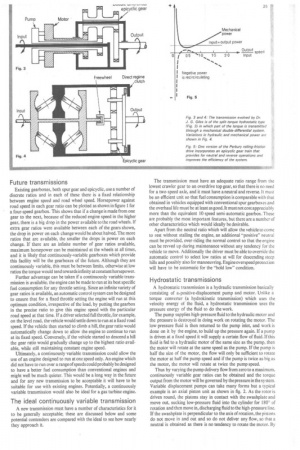
Thus by varying the pump delivery flow from zero to a maximum, continuously variable gear ratios can be obtained and the torque output from the motor will be governed by the pressure in the system. Variable displacement pumps can take many forms but a typical example is an axial piston unit as shown in fig. 2. As the rotor is driven round, the pistons stay in contact with the swashplate and move out, sucking low-pressure fluid into the cylinder for 1800 of rotation and then move in, discharging fluid to the high-pressure line. If the swashplate is perpendicular to the axis of rotation, the pistons do not move in and out and so do not deliver any flow, so that a neutral is obtained as there is no tendency to rotate the motor. By
moving the 'swastplate in the opposite direction, the flow through the pump is reversed and the motor rotates in the opposite direction to give reverse.
Hydrostatic transmissions can be arranged in two forms. The simplest of these is a gearbox replacement. As the name implies, a pump and motor, joined by short pipes, are mounted in a box which replaces the conventional gearbox. This provides all the advantages of a continuously variable automatic transmission but it does not exploit the full potential of hydrostatics in vehicles. To do this the pump would be mounted on the engine and connected by pipes to hydraulic motors in the wheel hubs. There would no longer be a propeller shaft or rear axle. This would give greater freedom in the design of vehicles but perhaps the most important factor is that power can be easily transmitted to any wheel on the vehicle itself or to trailer wheels, if this is required.
An automatic control system can be designed to meet most of the "ideal" requirements set out above and hydrostatic transmissions can be designed to give an adequate ratio range, including overdrive, and to have an acceptable life in service. The main problem with hydrostatics for vehicle transmissions is their efficiency. This can be quite high for part of the operating range but has a tendency to reduce, particularly at higher speeds, over other parts of the range. Cost, too, would be a problem initially, but in volume production there is no reason to suppose that it would not come down to an acceptable value for an equivalent system.
Split-torque hydrostatics
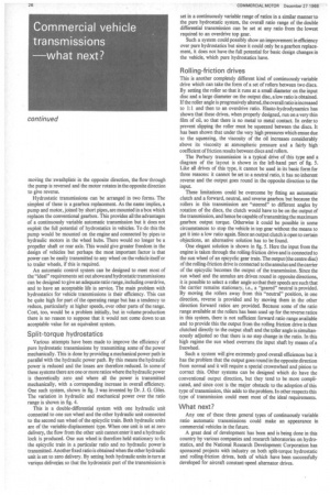
Various attempts have been made to improve the efficiency of pure hydrostatic transmissions by transmitting some of the power mechanically. This is done by providing a mechanical power path in parallel with the hydraulic power path. By this means the hydraulic power is reduced and the losses are therefore reduced. In some of these systems there are one or more ratios where the hydraulic power is theoretically zero and where all the power is transmitted mechanically, with a corresponding increase in overall efficiency. One such system, shown in fig. 3 was invented by Dr. J. G. Giles. The variation in hydraulic and mechanical power over the ratio range is shown in fig. 4.
This is a double-differential system with one hydraulic unit connected to one sun wheel and the other hydraulic unit connected to the second sun wheel of the epicyclic train. Both hydraulic units are of the variable-displacement type. When one unit is set at zero delivery, the flow from the other unit cannot enter it and a hydraulic lock is produced. One sun wheel is therefore held stationary to fix the epicyclic train in a particular ratio and no hydraulic power is transmitted. Another fixed ratio is obtained when the other hydraulic unit is set to zero delivery. By setting both hydraulic units in turn at various deliveries so that the hydrostatic part of the transmission is set in a continuously variable range of ratios in a similar manner to the pure hydrostatic system, the overall ratio range of the double differential transmission can be set at any ratio from the lowest required to an overdrive top gear.
Such a system could possibly show an improvement in efficiency over pure hydrostatics but since it could only be a gearbox replacement, it does not have the full potential for basic design changes in the vehicle, which pure hydrostatics have.
Rolling-friction drives
This is another completely different kind of continuously variable drive which can take the form of a set of rollers between two discs. By setting the roller so that it runs at a small diameter on the input disc and a large diameter on the output disc, a low ratio is obtained. If the roller angle is progressively altered, the overall ratio is increased to 1:1 and then to an overdrive ratio. Elasto-hydrodynamics has shown that these drives, when properly designed, run on a very thin film of oil, so that there is no metal to metal contact. In order to prevent slipping the roller must be squeezed between the discs. It has been shown that under the very high pressures which ensue due to the squeezing, the viscosity of the oil increases considerably above its viscosity at atmospheric pressure and a fairly high coefficient of friction results between discs and rollers.
The Perbury transmission is a typical drive of this type and a diagram of the layout is shown in the left-hand part of fig. 5. Like all drives of this type, it cannot be used in its basic form for three reasons: it cannot be set to a neutral ratio, it has no inherent reverse and the output goes round in the opposite direction to the input.
These limitations could be overcome by fitting an automatic clutch and a forward, neutral, and reverse gearbox but because the rollers in this transmission are "steered" to different angles by rotation of the discs, the clutch would have to be on the output of the transmission, and hence be capable of transmitting the maximum gearbox output torque. Otherwise it could be possible in some circumstances to stop the vehicle in top gear without the means to get it into a low ratio again. Since an output clutch is open to certain objections, an alternative solution has to be found.
One elegant solution is shown in fig. 5. Here the input from the engine is taken through the rolling-friction drive and is connected to the sun wheel of an epicyclic gear train. The output (the centre disc) of the rolling-friction drive is connected to the annulus and the carrier of the epicyclic becomes the output of the transmission. Since the sun wheel and the annulus are driven round in opposite directions, it is possible to select a roller angle so that their speeds are such that the carrier remains stationary, i.e., a "geared" neutral is provided. By moving the rollers away from this "neutral" position, in one direction, reverse is provided and by moving them in the other direction forward ratios are provided. Because some of the ratio range available at the rollers has been used up for the reverse ratios in this system, there is not sufficient forward ratio range available and to provide this the output from the rolling friction drive is then clutched directly to the output shaft and the roller angle is simultaneously adjusted so that there is no step change in the ratio. In this high regime the sun wheel overruns the input shaft by means of a freewheel.
Such a system will give extremely good overall efficiences but it has the problem that the output goes round in the opposite direction from normal and it will require a special crownwheel and pinion to correct this. Other systems can be designed which do have the conventional output direction, but they tend to be more complicated, and since cost is the major obstacle to the adoption of this type of transmission, this adds to the problem. In other respects this type of transmission could meet most of the ideal requirements.
What next?
Any one of these three general types of continuously variable ratio automatic transmissions could make an appearance in commercial vehicles in the future.
A great deal of development has been and is being done in this country by various companies and research laboratories on hydrostatics, and the National Research Development Corporation has sponsored projects with industry on both split-torque hydrostatic and rolling-friction drives, both of which have been successfully developed for aircraft constant-speed alternator drives.