


Two-unit Frame for Distortion Insulation
Page 28
If you've noticed an error in this article please click here to report it so we can fix it.
A Resume' of Patent Specifications that Have Recently Been Published
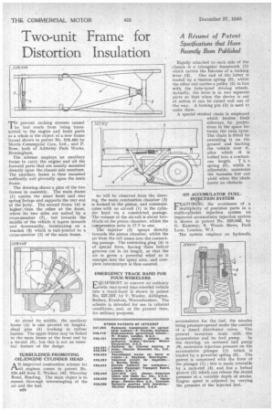
'TO prevent racking stresses caused 1 by bad roads from being transmitted to the engine and front parts as a whole is the object of a new frame layout shown in patent No. 528,496 by Morris Commercial Cars, Ltd., and P. Rose, both of Adderley Park Works, Birmingham.
The scheme employs an auxiliary frame to carry the engine and all the forward parts that are usually mounted directly upon the chassis side members. The auxiliary frame is then mounted resiliently and pivotally upon the main frame.
The drawing shows a plan of the two frames in assembly. The main frame (1) carries the usual front and rear spring fixings and supports the rear end of the body. The second frame (4) is higher than the other atthe front, where its two sides are united by a cross-member (7), but towards the middle of the vehicle it tapers inwards and downwardly, terminating on a bracket (3) which is ball-jointed to a cross-member (2) of the main frame.
At about its middle, the auxiliary frame • (4) is also pivoted on longitudinal pins (5) working in rubber bushes. The upper frame may be linked to the main frame at the front end by a tie-rod (6), but this is not an essential feature of the design.
TURBULENCE-PROMOTING OIL-ENGINE CYLINDER HEAD
AN improved combustion scheme for oil engines comes in patent No. 528,448 from E. Walker, 192, Waverley Road, Reading. The main object is to ensure thorough intermingling of the air and the fuel.
1320 As will be observed from the drawing, the main combustion chamber (3) is formed in the piston, and communicates with an air-cell (1) in the cylinder head via a constricted passage. The volume of the air-cell is about twothuds of the piston chamber, whilst the compression ratio is 17.7 to one.
The injector (2) sprays directly towards the piston chamber, whilst the air from the cell issues into the connecting passage. The restricting plug (4) is of special form, having three helical grooves cut in its length, so that the air is given a powerful whirl as it emerges into the spray area, and complete intermixture is thus assured., EMERGENCY TRACK BAND FOR FOUR-WHEELERS
EQUIPMENT to convert an ordinary twin rear-tyred four-wheeled vehicle into a track-layer is shown in patent No. 527,507, by V. Wasley, Aldington, Badsey, Evesham, Worcestershire. The scheme is intended for use in colonial conditions, and, at the present time, for military purposes.
Rigidly attached to each aide of the chassisis a triangular framework (I) which carries the fulcrum of a rocking lever (4). One end of the latter is loaded by a tension spring (5), whilst the other end carries a pulley (2) in line with the twin-tyred driving wheels. Actually, the lever is in two separate parts so that when the device is out of action it can be raised well out of the way. A locking pin (3) is used to unite them.
A special straked chain is employed which locates itself sideways, by projections in the space between the twin tyres. The chain is fitted by extending it on the ground and backing the vehicle over it, after which it is bolted into a continuous length. T h e spring (5), whieh is adjustable, maintains the tautness but can yield when the -chain meets an obstacle.
AN ACCUMULATOR FUELINJECTION SYSTEM FEATURING the avoidance of a multiplicity of precision parts in a. multi-cylinder injection system an improved accumulator injection system is shown in patent No. 528,042, by G. Kammar, 6, Woods Mews, Park Lane, London, W.1.
The system employs an hydraulic accumulator for the fuel, the nozzles being pressure-opened under the control of a timed distributor valve. The present invention deals with the accumulator and its feed pump. In the drawing, an untimed fuel pump (6) maintains injection pressure on the accumulator plunger (1) which is loaded by a powerful spring (5) . The patent is concerned with the form of the plunger (1) ; this is made rotatable by ,a rack-rod .(4) and has a helical groove (2) which can release the stored pressure at a variable depth of stroke. Engine speed is adjusted by varying the pressure of the injected fuel.