


The Latest Borg and Beck Clutch
Page 46
If you've noticed an error in this article please click here to report it so we can fix it.
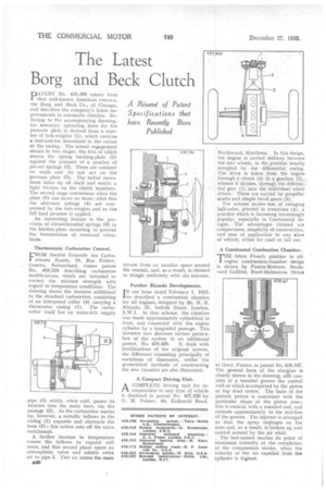
PATENT No. 438,396 comes from that well-known American concern, the Borg and Beck Co., of Chicago, and describes the company's latest improvements in automatic clutches. Referring to the accompanying drawing, the necessaryoperating force for the pressure plate is derived from a number of bob-Weights (1), which exercise a heel-and-toe movement in the corner of the casing. The actual engagement occurs in two stages, the first of which moves the spring backing-plate (2)
• against the pressure of a number of pm-set springs (3). These are confined on studs and clo not act on the pressure plate (5). The initial movement takes up all slack and exerts a light friction on the clutch "members. The second stage commences when the plate (5) can move no more; after this the alternate springs (4) are compressed by the bob-weights and so the full load pressure is applied.
An interesting feature is the provision of circumferential springs (6) in the friction-plate mounting to prevent the transmission of torsional vibrations..
Thermostatic Carburetter Control.
FROM Societe Generale des Carbureteurs Zenith, 10, Rue Petitot, Geneva, Switzerland, comes patent No. 438,319 describing carburetter modifications, which are intended to correct the mixture strength with regard to temperature conditions. The drawing shows the features additional to the standard carburetter, consisting of an interposed collar (4) carrying a thermostat casing (1). The carburetter itself has an extra-rich supply . pipe (2) which, when cold, passes its mixture into the main bore, via the passage (5). As the carburetter warms up, however, a metallic bellows in the casing (1) expands and obstructs the bore (5) ; this action cuts off the extra enrichment.
A further increase in temperature causes the bellows to expand still more, and this second phase opens an atmospheric valve and admits extra air to pipe 3. This air enters the main
B40
stream from an annular space around the venturi, and, as a result, is claimed to mingle uniformly with the mixture.
Further Ricardo Developments.
IN our issue dated February 1, 1935, we described a combustion chambei for oil engines, designed by Mr: H. R. Ricardo, 21, Suffolk Street, London, S.W.1. In that scheme, the chamber was made approximately cylindrical in form, and connected with the engine cylinder by a tangential passage. This inventor now discloses further particulars of the system in an additional
patent, No. 438,429. It deals with modifications of the original system, the difference consisting principally of variations of dimension, whilst the geometrical methods of constructing the new chamber are also illustrated.
A Compact Driving Unit.
ACOMPLETE driving unit for incorporation in any type of vehicle is disclosed in patent No. 437,80 by G. M. Palmer, 53, Hallowell Road, Northwood, Middlesex. , In this design, the engine is carried midway between the rear wheels, in the position usually occupied by the differential casing. The drive is taken from the engine through d' clutch (3) to a gearbox (2), whence it divides, through the differential gear (I) into the individual. wheel drives. These are carried by propeller shafts and simple bevel gears (5).
The scheme makes ease of swinging half-axles, pivoted in trunnions (4), a practice which is becoming increasingly popular, especially in Continental designs. The advantages claimed are compactness, simplicity of construction, and ease of application to any slass of vehicle, either for road or rail use.
A Continental Combustion Chamber.
THE latest French practice in oilengine combustion-chamber design is shown by Fusion-Moteurs, Boulec yard Gallieni, Rueil-Malniaison (Seine
et Oise), France, in patent No. 438,167. The general form of the cha%ber is clearly shown in the drawing, and consists of a toroidal groove the central wall of which is completed by the piston at top dead centre. The basis of the present patent is concerned with the particular shape of the piston nose ; this is conical, with a rounded end, and extends approximately to the mid-line of the groove. The injector is arranged so that the spray impinges on the nose and, as a result, is broken up and carried around by the air whirl.
The last-named reaches its point of maximum intensity at the completion of the compression stroke, when the velocity of the air expelled from the cylinder is highest.